Topics
Background
The early Morgan 3-wheelers were all very light and relatively simple machines.
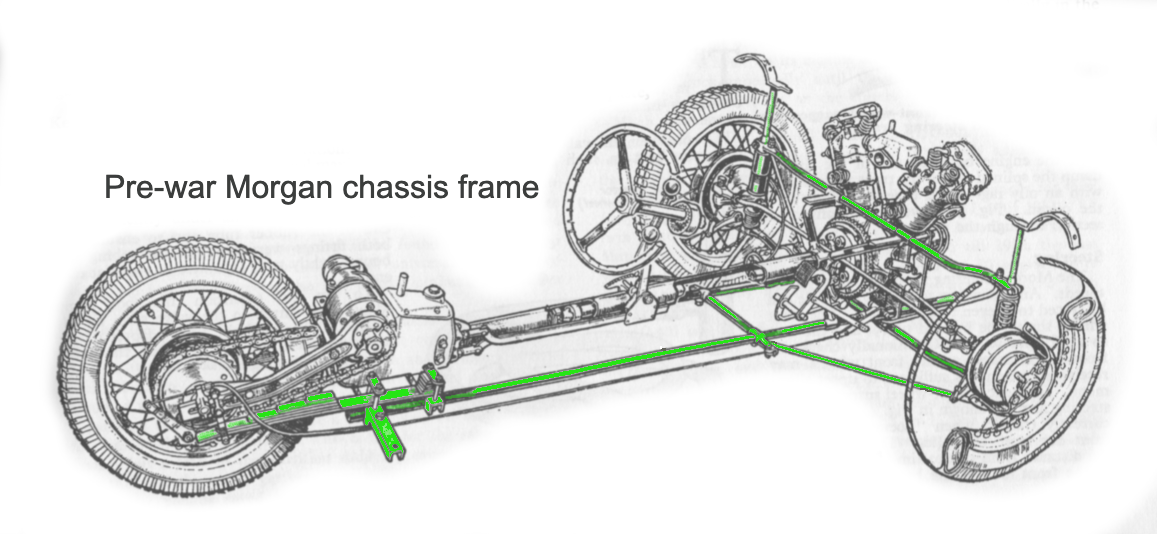
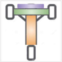
Morgan ladder chassis circa 1930 (green highlights steel frame including leaf spring rear support)
The steel that supports the suspension and body is surprisingly sparse: basically two parallel bars in an “H” ladder frame with a few attachments to hold up the mudguards and stabilize the wheels. The aluminum skin is primarily held in place with an extensive laminated wood skeleton.

Cut-away model showing wood frame supports for aluminum body (courtesy of David Jones)
While the new Morgan 3-wheeler retains some wood parts, the chassis has now evolved into a modern space frame design … and for good reason.
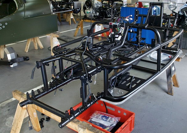
Morgan 3 space frame (Speedhunters)
Modern suspension, steering, and brake systems produce significantly different frame stresses, as do much higher horsepower engines. What once resembled a bicycle frame grafted onto a 19th century English carriage has now evolved into a high strength space frame to handle a new set of design challenges.
While our Aero Moto™ exterior skin will closely resemble the vintage pre-war cyclecars, our unseen chassis will be quite different as we follow the development path suggested by Morgan’s recent experience.
Space frame
The space frame conceptually followed the early 20th century ladder construction. Well designed space frames arrange tubular section to handle either tension or compression forces. The majority of bespoke vehicles use space frames because they can be made in small production runs.
In contrast, a monocoque one-piece chassis is used by almost all major car manufacturers today (but not Morgan!) since it can be mass produced in an automated assembly.
Front
The front engine bay section of the frame has mounting points for a double wishbone (also referred to as A-arm) suspension, shock absorbers, steering rack, and — of course — the engine block. In addition, there are pads for mounting the large front headlights and turn signal indicators.
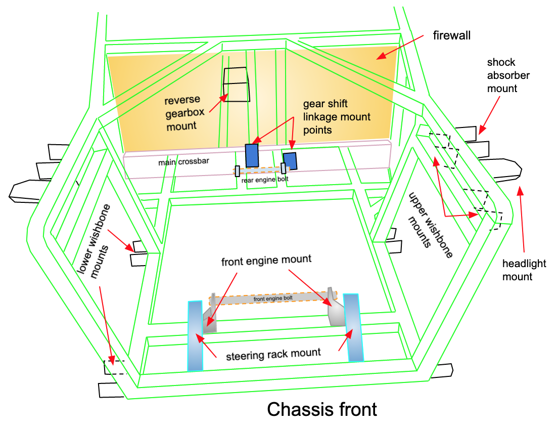
Aero Moto front space frame design with major mounting points
Just behind the rear engine bolt mount are two brackets for the gear shift linkage. Beyond the firewall separation, a separate box-like mount is provided for the reverse gearbox.
Double wishbone suspension
A double wishbone suspension utilizes A-shaped arms; each arm has two mounting points on the chassis and one joint at the knuckle that locates the wheel. The shock absorber connects to the frame and bottom wishbone.
Double wishbone designs are expensive but enable more precise control the motion of the wheel throughout suspension travel via camber angle, caster angle, toe pattern, roll center height, and scrub radius. Most high performance vehicles use this kind of setup.
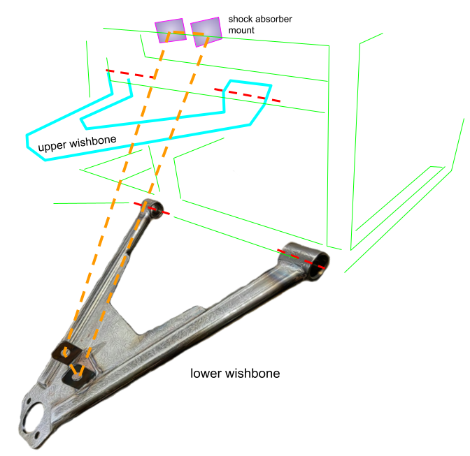
Wishbone and shock positioning on frame
The bespoke wishbone design is fabricated using a TIG welder.
Cockpit
The front and rear sections of the frame are separated by a firewall in the front and a bulkhead in the rear that defines the cockpit area with a tunnel running up the middle.

Cockpit with dash and center tunnel
The dash has a camel double hump shape that follows the fiberglass scuttle cover contour.
Bulkhead
A bulkhead separates the cockpit from the rear section of the frame.
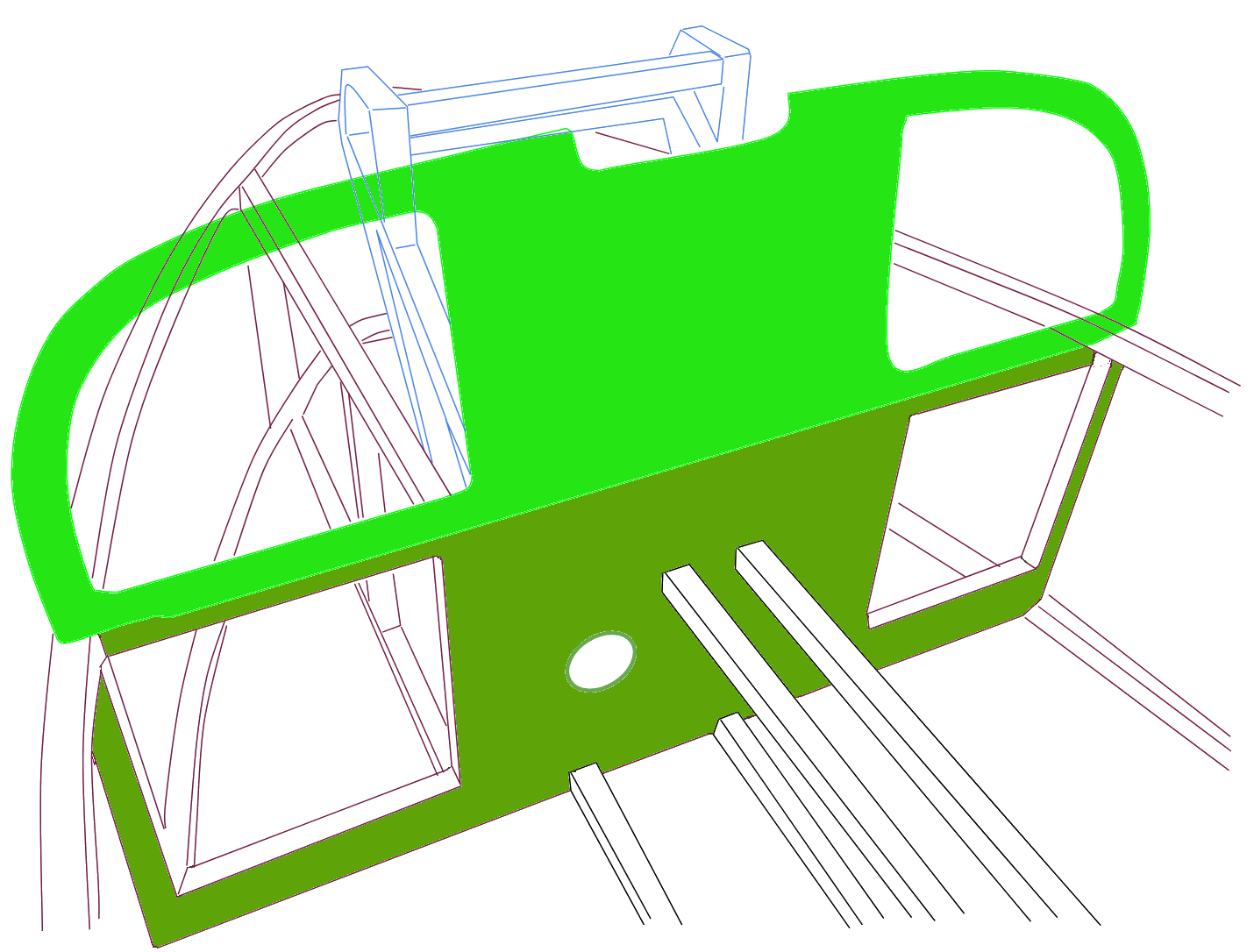
Aero Moto rear bulkhead (blue lines indicate shock tower support)
Steel bar supports for the tunnel extend out from the bulkhead. The circular cutout is the pass-through for the drive shaft/swing arm U-joint mating. The suspension tower for the rear twin shock absorbers is behind the bulkhead and surrounded by the beetleback curved bar infrastructure.
Rear
The rear suspension, unlike the front, is borrowed from the Moto Guzzi motorcycle, including the swing arm, bevel gear, and rear wheel. Two brackets are provided for new twin rear shock absorbers which are required because the original Guzzi ones are too short. The swing arm pivot pins fit into either side of the frame much like on the original cycle. The drive shaft U-joint that originally connected directly to the transmission gear poking through the engine case now fits into a rear wall mount where it joins an extended drive shaft.

Aero Moto rear with major mounting points
Note that the rear rounded beetleback end of the frame can be detached to facilitate servicing of the rear wheel without the need to lift the entire chassis.