Topics
Background
After all the preliminaries followed by the removal of the rear wheel, swing arm and transmission, harness, and lower rails on the frame, it is, theoretically, an easy operation to remove the front and rear engine mounting bolts to lift the entire chassis over the engine.
“Frankenstein” stuck bolt in front mount
The theory doesn’t contemplate completely stuck mounting bolts. In our case, the front steel bolt was fused to the aluminum front cover housing in a chemical process just below welding in terms of bonding strength.
This unfortunate situation required cutting through a bit of the left lower rail (but leaving the engine itself completely untouched) to free that side of the frame. It was then possible to free the other side, but not before leaving a rod sticking out of both sides of the front mounting hole!
Engine removal
Once the engine is separated from the frame, an engine hoist fitted with straps quickly positions the block on a work table.
Engine out and placed on a work table
When the back of the gearbox is braced, the entire assembly is stable.
Frankenstein stuck bolt adventure

STEP 1: Hot coke bath for the front cover
The good news is that the front mount bolt passes through only the aluminum front cover, and not the entire bottom of the engine block itself. The front cover is easily removed by first taking off the black plastic alternator cover (we will replace this with a chrome one) and then the alternator itself.
There are three possible solutions: 1] buy a new front cover (they may be still available in limited numbers or as used, but not damaged, parts); 2] use chemicals to free up the bond between the steel rod and the aluminum; 3] drill out the steel rod without damaging the aluminum housing.

STEP 2: using a 12 ton press
We started with chemistry. The most cheapest Old School method to try first is, believe it or not, a hot bath of Diet Coke. The phosphoric acid eats away rust (and teeth, by the way) and may leave enough of a gap to hammer or press the rod out. After a day soaking in the Coke, we tried tapping the rod, and then attempted to pressed it out with a 12 ton hydraulic press. No joy.
The next chemical to try is potassium aluminum sulfate or KAl(SO4)2, a common inorganic salt sometimes called alum and used to make vegetables more crisp; as such it is often sold in supermarkets. When some heat is applied, alum will dissolve steel but won’t impact aluminum at all.
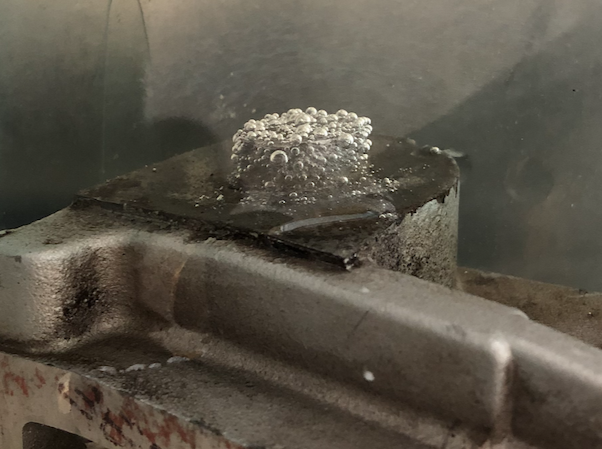
Oxygen bubbles in alum solution
As the alum eats away at the steel, one byproduct is oxygen. Little bubbles formed around the bolt ends, so at least a chemical process, albeit a very slow one, could be directly observed.
A little heat is necessary to completely dissolve the alum powder in water: four tablespoons for each cup of water. In our case, three cups completely immersed the front cover bottom with the stuck bolt. But it wasn’t enough. After 24 hours, the bolt wouldn’t give.

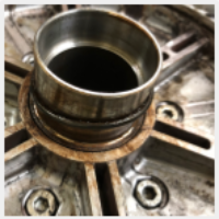
Cover mounted for drilling on the mill
So Bruce applied his machinist skills, setting up the mill to precisely drill out the stuck bolt with such accuracy that there isn’t a scratch on the inside of the cover’s mounting hole.
The mill setup required fixing the cover with to a 90-degree mounting block with C-clamps.
When the exact center of the stuck bolt was determined, the mill’s drill bit carefully carved out the fused steel material.
The chemical treatments may have freed up some of the steel bolt surface fusing, but the complete solution required the precision drilling only possible with a mill.
A victory and a lesson that anything can be solved with the right tools.
Exterior restoration
The coating of oily grime can be scrubbed off with a wire brush and some denatured alcohol.

Initial cleaning with wire brush and denatured alcohol
Initial cleaning helps to identify problem areas that will require more intensive restoration later on.
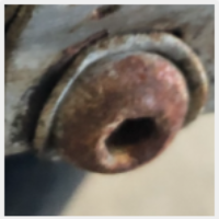
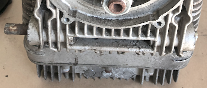
Magnetic catch plug

In the crankcase bell housing, just below the starter bulge in the engine block, is a magnetic hex catch plug (part number 30003770) and standard oil plug washer designed to prevent shards caused by starter gear grinding from reaching the ignition pickup under the right injector and therefore impacting ignition (on carburetor models, the same issue applies by the way).
After the plug thread is a long magnetic rod that attracts bits of metal away from the flywheel surface.
Damaged or incorrect catch plug inside housing
Ironically, when the V-twin motor is installed on the California 1100 chassis, it is impossible to unfasten and check this plug for debris! We will endeavor to make this plug more accessible on our Aero Moto.
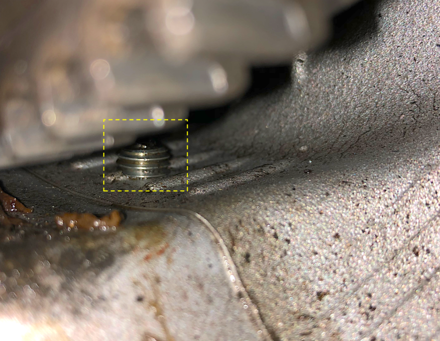
Incidentally, our plug only had a small magnetic nib at the end; the long magnetic rod apparently either rusted away, broke off sometime during the past quarter century, or the original long magnetic plug was swapped out by a prior owner for a standard oil sump drain plug that just has the magnetic nib.

Correct magnetic catch plug installed
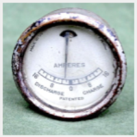
The California 1100i flywheel sensor, opposite from the magnetic catch plug, is critical for engine performance. The magnetic plug was probably specified by Moto Guzzi to prevent bits of metal from causing flywheel sensor signal errors.
Interestingly, on post-2000 California models with the updated 16M ECU, the flywheel sensor is eliminated and so is the magnetic catch plug.
Cleaning the plug can be conveniently combined with oil changes (as long as plug access isn’t blocked by the chassis).
Prep for refinish

Covers to protect the exhaust outlet
The motorcycle engine has no convenient place to mount it to an engine hoist, and it’s too heavy to simply carry around. We choose to place the entire engine and gearbox in a plastic tub on a table top so that degreaser and water rinse could be applied with a minimum of mess.
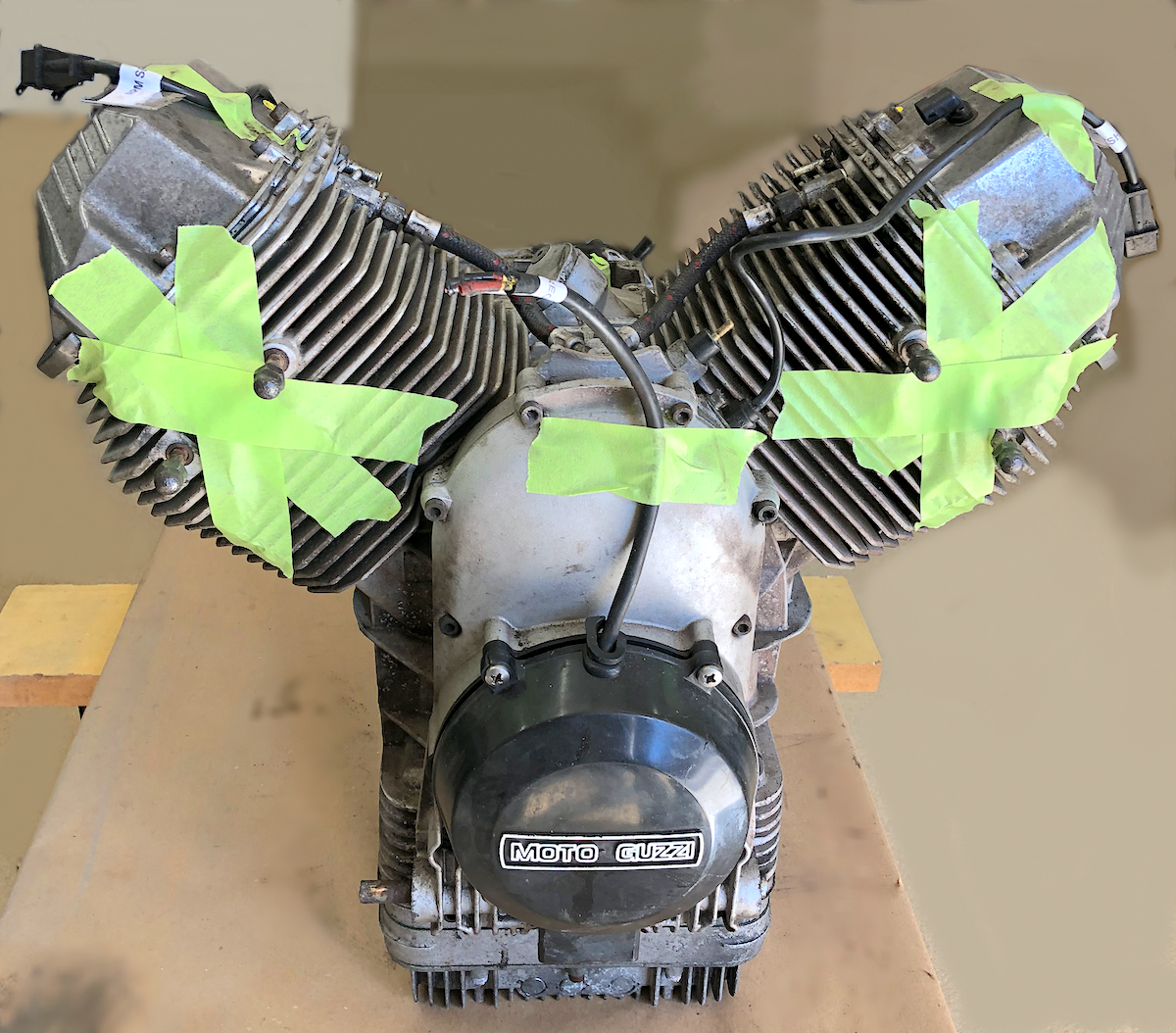
All the openings were covered over — the intake and exhaust outlet holes, breather openings, starter motor mount, and so on — to prevent dirt and chemicals from getting into the engine internals. With everything battened down, the deep clean prep can begin.
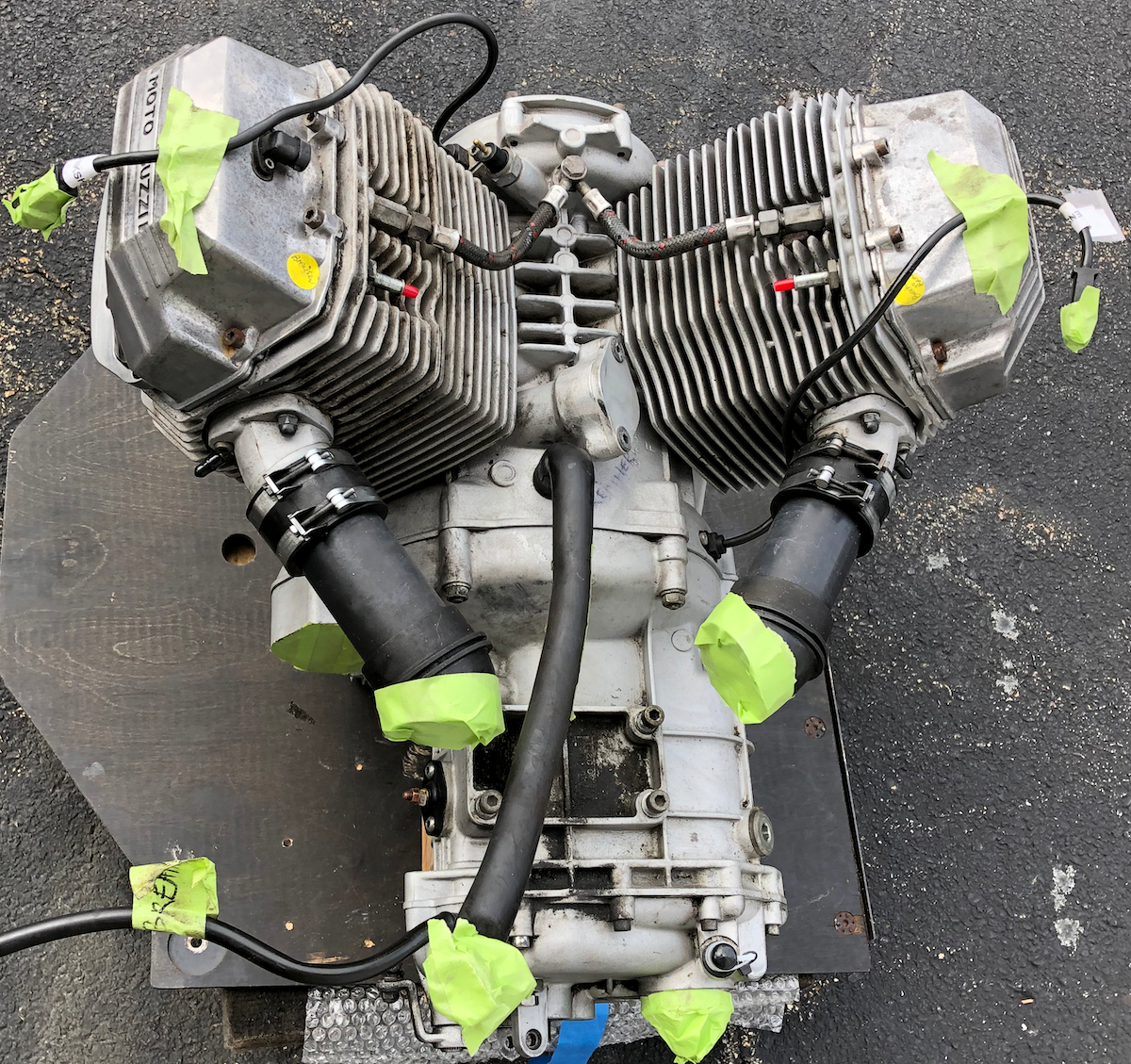
Engine ready for degreaser prep and hose wash down

Engine and gearbox in plastic tub ready for deep cleaning; openings covered with tape or tubing
Small removable parts were sandblasted, but the main crankcase and cylinder heads were cleaned with solvent, water, and a lot of wire brushing.
Aluminum paint
POR15 aluminum engine paint restores the metal back to its original factory appearance.

Road grime condition versus factory-like restoration
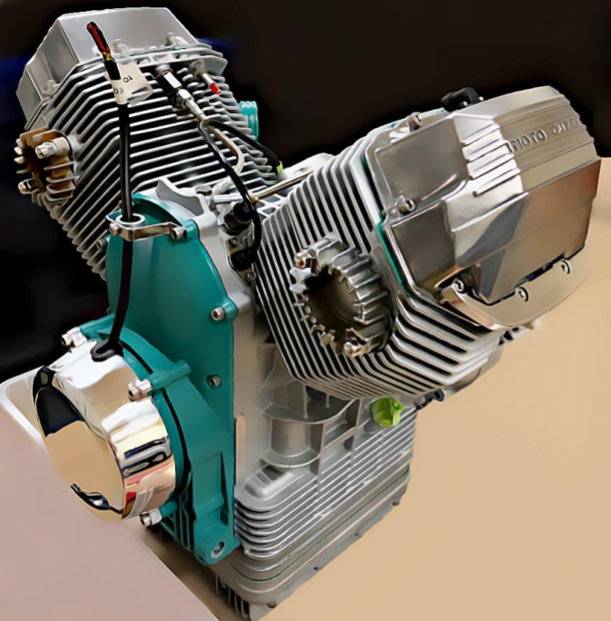
Green cover
We used Jaguar pale green engine paint to highlight the front timing cover and added a polished aluminum alternator cover.

Pale green timing cover with polished alternator cover
See details below about the M16 alternator nut.
Alternator wire holder

Wire holder extends from cover top
We decided to fashion an alternator wire holder mounted to the top of the timing cover.
On the Guzzi California motorcycle, the black wire from the alternator runs straight up to the top of the fork and connects to the voltage regulator. The cyclecar must use a different layout farther behind the cylinders so instead of the alternator wire just flapping around the front of engine, this holder makes harness routing a little easier.
Another option is to mount the alternator upside down so that the wire exits from the bottom, an idea we will explore later.
Alternator M16 nut

L-bracket flywheel lock
To remove and install the timing cover plate, it is necessary to first unfasten and tighten, respectively, the M16 nut that holds the alternator to the shaft. This nut should be torqued to 75-80 Nm and to do so, the shaft must be prevented from turning.
A simple flywheel lock can be fashioned with a small piece of steel 1/8″ L-bracket clamped to the edge of the starter motor opening. When one of the teeth is engaged in the L-bracket, the flywheel will not rotate and the bracket is strong enough to enable the alternator nut to be properly torqued.
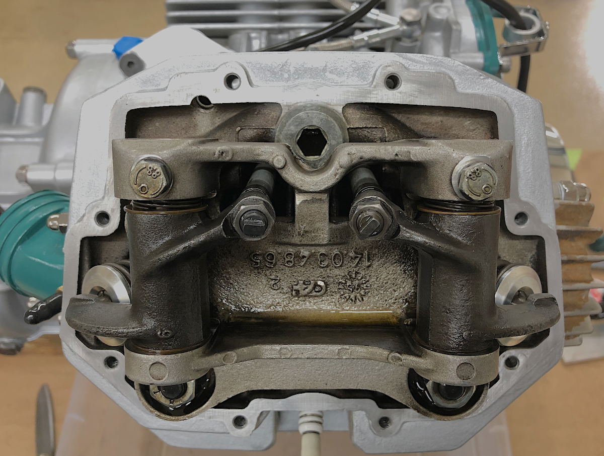
Valves and covers
Valve clearance
When the covers are off for polishing, it’s convenient to check valve clearances on each cylinder: recommended specification is 0.004″ intake and 0.006″ exhaust for US exports (note that non-US bikes use the metric system specifying 0.10mm and 0.15mm respectively which is slightly tighter).
Remove the alternator cover and spark plugs, then rotate the shaft (using the M16 nut) clockwise to top dead center (TDC). With the thumb placed over the spark plug hole, outward air pressure indicates the compression cycle and the timing mark, viewed on the right side inspection hole, will show either “D” or “S” (Destra is Italian for “right” and sinistra for “left” cylinders respectively).

Inspection hole timing marks for left and right cylinders
The appropriate feeler gauge should just fit into the space between the rocker arm and the valve stem with a little friction “grab”.
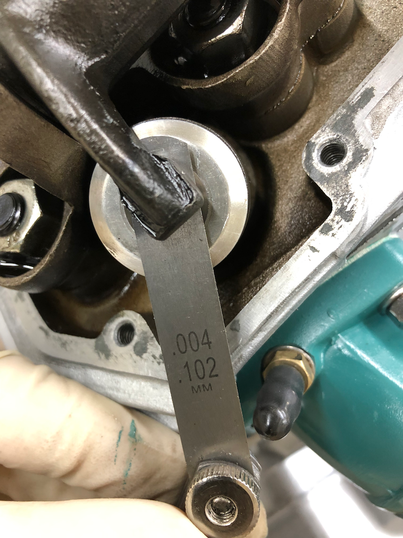
Intake clearance of 0.004″

Exhaust clearance of 0.006″
Note that the next thicker feeler should NOT fit through at all.
Gaskets
New gaskets are fitted after any removal of the valve covers. Cleaning off the old gasket can be troublesome. Dipping 1500 grit sandpaper in denatured alcohol typically works well.
Gasket surface cleaned with 1500 grit and denatured alcohol
Gaskets generally should not be fitted “dry”; we prefer Hylomar Blue sealant applied on both sides of the gasket.
Polishing covers

Cleaning out the “Moto Guzzi” lettering
The aluminum valve covers can be polished to a pleasing chrome-like finish following a thorough cleaning.
After a quarter century, grime is securely embedded in all the little pockets and crevices, including the bas relief Moto Guzzi lettering. A small brush and dishwashing soap remove surface oils and dirt.
We used with a deoxidizer and then finished polishing by hand. Covers that have surfaces scratches must be sanded down first with progressively fine grit paper.
BEFORE

Cleaned valve cover before de-oxidation and polish
AFTER
The left cover has a temperature sensor embedded into the cover so care must be taken not to damage it (remove before cleaning).

Hand polished cover
Completed restoration
The exterior restoration is complete except for a new dipstick, re-chromed exhaust header collars, and the oil sump configuration (which will wait until the engine is mounted in the new cyclecar chassis).
Moto Guzzi 1046cc V-twin
All nuts and bolts were replaced with stainless steel, and more robust Nord-Lock® washers were installed instead of the original Guzzi single lock washers on M8 bolts/studs.