Topics
Background
The Aero cyclecar will reuse the Moto Guzzi swing arm, a fork-like structure that helps drive the rear wheel with the U-joint carrier bearing and two side pivot bearings, along with the bevel gear and transmission housing affixed to the rear wheel.

The swing arm left end directly supports the axle shaft that passes through the hub of the rear wheel; a nut fastener is on the right end of the axle shaft. A small clamping pin tightens the axle in place.
A spacer helps align a support for the brake caliper. The right end of the arm is shorter to fit into bevel gear that drives the rear wheel. Above the axle assembly is a mount for the left shock absorber; the right shock absorber mounts directly on the transmission housing.
Due to the different dimensions of the cyclecar chassis, new longer rear shocks will be fitted.
Rear wheel
The entire rear wheel assembly will be reused. Our rear tire is almost new and hopefully the tread pattern will work well. Fasteners, seals, and bearing can be replaced, as well as the brake disc if it has excessive wear.

If necessary, spoke repairs can be made on the wheel.
To remove the rear wheel, first completely remove the front/rear brake system including the proportioning valve, the master cylinder, and the rear caliper.
Deflate the tire to make it easier to wiggle off the swing arm ends. Loosen the axle clamping pin on the left side, remove the axle cover on the right, and then gently tap out the axle from the right side. Loosening the left shock absorber may also help provide more clearance for the tire.
With the caliper off, remove the caliper bracket to create a clearance space on the left side. Carefully pull the wheel towards the left side to free it from the transmission/bevel gear.
Drawing corrections
The official Moto Guzzi exploded rear wheel parts drawing can be confusing.

The spacer (indicated by “27”) appears to be on the outside of the wheel hub; note that the spacer does not have a collar as depicted in the official drawing. The correct placement is between the two wheel bearings (both marked as “7”). A center tube and circlip — the bearing carrier sleeve — is not identified; presumably it was once number 18 but removed for some reason. Fortunately this part does not need to be replaced in our case. The O-ring (“21”) is placed on the outside of this carrier sleeve and is compressed by the coupling disc (“22”).
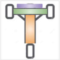
Bearing spacer
![]()
Bearing are positioned by their inner races, not the outer ones. The rear wheel spacer touches the inner race surface and, as the flange is fastened to the primary wheel hub, the two opposing races are properly aligned. The rear axle passes through the races and spacer tube. Spacers that are the wrong length or not properly installed will cause the inner race to be out of alignment with the outer race, leading to premature bearing failure.
The bearing on the brake disc side (left) is retained by a circlip. There is no circlip on the bevel gear (right) side.
Swing arm
Several swing arm parts degrade with age — including the bearings, U-joint coupling, and seals — and require replacement.
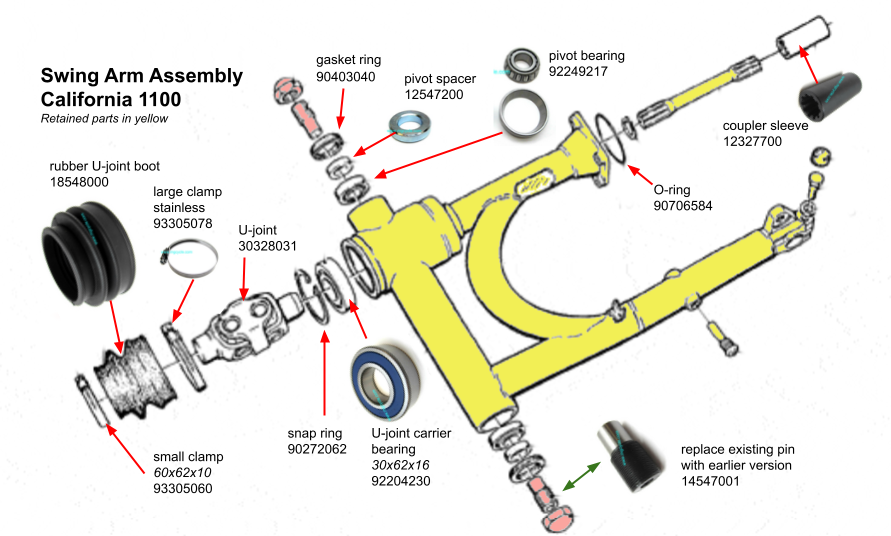
The rubber boot that covers the U-joint end of the swing arm may not be necessary since the swing arm will attach to the cyclecar chassis (and an extended drive shaft) and not to the engine directly.
Note that the cyclecar mount will use the older style pivot pin (same bearing size but different thread).
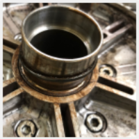
Transmission / bevel gear
The transmission housing and the bevel gear may need refreshment of various plugs, washers, seals, and other hardware.
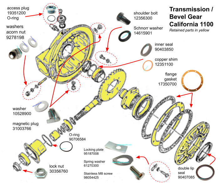
Fortunately, replacement parts are still readily available. In our case, only the acorn nuts holding the transmission to the swing arm were rusted; we substituted Nord-Lock® washers, too. Otherwise, the unit is in good condition and only required cleaning and fresh paint.

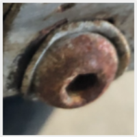
Painted and greased bevel drive (note red grease on bearing)