Topics
Background
While much of the original Moto Guzzi electronic engine (EFI) functionality will be retained in the cyclecar, the actual physical layout obviously does not conform to the new chassis and vehicle footprint.
When removed from the frame, the harness resembles a snake’s nest with a jumble of connectors, thick loom branches, and isolated wire strands sticking out everywhere. New solid state electronics can reduce this chaos significantly.
A good way to begin making sense of the tangled mess is to label everything and lay out the harness on an “autopsy table”. For clarity, we have also connected some non-harness parts, like the fuel pump, filter, breathers, and throttle body.
Keeping the entire harness more or less intact helps too, and also aids the task of removing the engine from the cycle frame infrastructure.
Wiring diagram
Click 1996-97 California 1100i wiring diagram for a PDF of the full harness layout. Our Guzzi has added 12-volt accessory outlets and a trickle charger plug, but is otherwise unaltered.
Fuse panel
The California 1100i harness includes six fuses and six relays packaged into a single panel “bar”, plus a separate round flasher wedged in a rubber vibration mount.
PANEL LAYOUT
- R1 – starter relay
- R2 – horn relay
- R3 – side kickstand relay
- R4 – headlight relay
- F1 – 4-way flasher fuse
- F2 – turn signals and running lights fuse
- F3 – brake light (right foot pedal), horn, starter solenoid fuse
- F4 – brake light (hand lever), headlights, charging system, tach, dash indicators fuse
- R5 – injectors and ECU relay
- F5 – fuel pump relay, injectors, ECU power fuse
- F6 – fuel pump motor, ignition coils, control modules fuse
- R6 – fuel pump and ignition relay
- flasher not shown in drawing
ECU connector
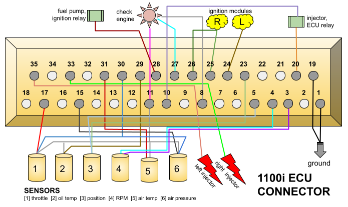
The computer that controls the electronic fuel injection system, the ECU, is connected to the harness via a 35-pin plug.
All basic engine operations flow through the ECU with integrated relays, sensors, and other components.
Check engine lamp
An IAW auto-diagnostic fault detection system is incorporated into the P9 version of the ECU. Fed by pins 8, 11, and 27, an LED on the dash and/or a pigtail with a Molex 1396 connector near the ECU (which can be connected to a reader) displays error codes. Compared to current technology, this diagnostic is rather primitive, but it does provide some useful data. The dash LED flashes normally during engine start. As long as the ignition is ON, all fault codes and prior history is retained in ECU memory. Turning off the ignition erases all data.
There are seven diagnostic codes defined by the timing and number of LED flashes. Each code begins and ends with a series of short pulses. In between these quick pulses are longer flashes separated by a long pause. Thus, two long flashes followed by a long pause and then followed by a single long flash is code 2.1.
Code interpretation
- 1.1 – RPM data failure
- 1.2 – timing position data failure (TDC)
- 1.3 – incompatible RPM or timing data
- 2.1 – air temperature data failure
- 2.3 – oil temperature data failure
- 3.2 – barometric air pressure data failure
- 3.3 – throttle poteniometer data failure
Startup circuit
Starting the engine involves a number of switches and relays, some installed for a better safety margin of motorcycle operation (but not relevant to our cyclecar).
Turning the ignition key ON allows battery current to flow to the kill switch and to fuse 3 … but nothing else happens. If the kill switch is ON, battery current then activates the stand relay, but only if the kick stand is up (otherwise nothing else will happen).
The activated stand relay in turn triggers both injector/ECU and starter relays. The activated injector/ECU relay allows fused positive current — already switched with the ignition key ON position — to start the ECU, power up the injectors, and initialize the fuel pump/ignition relay to start the fuel pump.
Meanwhile, the starter relay, activated by a feed from the stand relay, has made the start button ready for action. Pushing the start button initializes the starter solenoid, and the engine turns over.
Switch re-purposing
Two switches in the startup circuit — the side stand microswitch and kill toggle — are specific to motorcycle operation. The stand switch prevents riding off with the kickstand deployed, an obvious safety issue. The rationale behind the so-called kill switch is less clear; many agree this is a handlebar convenience for shutting down the engine instead of forcing a rider to let go of the handlebar and search for the ignition key. Neither switch is necessary for the cyclecar.
Parking brake
Obviously motorcycles don’t have parking brakes (they have parking stands instead). Our cyclecar will have a parking handbrake and, to prevent driving off with the brake set, the side stand switch could be re-purposed as a handbrake cutoff. Only if the handbrake is released would the engine start (for safety, the foot brake pedal would be depressed as well at engine start).
Hidden vehicle lock
The kill switch functionality could be re-purposed as a vehicle lock to prevent unauthorized engine start. The switch could be placed behind a locking cubby (glovebox) door or hidden somewhere under the dash.


