Topics
Background
With the ultimate goal of removing the 1046cc V-twin engine and harvesting assemblies that will be “recycled” into the new vehicle, the Moto Guzzi California 1100i is dismantled piece by piece.
First, the windshield, luggage side bags, top case, rear support rack and seat along with the taillight assembly were removed. The front seat, side covers, left passenger foot peg was also taken off to allow a closer inspection and evaluate the original condition.
Battery and ECU

ECU version P8 after a little polishing
The battery and ECU are both tucked under the front seat that can be easily removed by turning the key on the left side (in our case, the latch was stuck with excess grease and had to be moved manually) to open a holding latch mechanism.
The ECU was connected on the right side with a large plug covered in grease and grim. The battery can simply be lifted out of its hold — it was not fastened down — after a few wires are pushed out of the way.
The battery will be replaced, possibly one with lithium chemistry. The ECU, on the other hand, is a critical component of the EFI system and must be preserved without modification. After cleaning and a little polishing, the ECU has a respectable appearance.
Fuel tank and air filter

Fuel tank bolt (green material is an “air filter”)
Just forward of the battery cavity is a bolt that holds the trailing edge of the fuel tank. Remove this bolt and then shutoff both side petcocks to stop the flow of gasoline out of the tank. Disconnect the dual fuel hoses as well as the electrical connector for the fuel level gauge. At the front neck of the tank is a breather tube to remove, too.
With these preliminaries completed, lift the rear tank tab (where the bolt was removed) about 1/2″ and place a small wood block to hold the position. Then very gently use a small crowbar to slowly push the tank forward about one inch from its round front neck. At this point the tank should be free of dual hockey-puck-like rubber mounts on the left and right undersides and can be lifted away from the frame.

Filter cover and wiring harness under the fuel tank
In lieu of a proper air filter, our Guzzi sported a decidedly homemade one made out of some kind of ugly green plastic mesh!

Airbox housing under the air filter with seat plate
The air filter cover is fastened with three bolts that fit into nutserts embedded into the large black plastic airbox housing. The bottom of the airbox has two outlets that are connected to the throttle body via large circular ducts.
The front section of the under-fuel tank area contains a tangle of hoses and much of the wiring harness for the engine, most of it zip-tied to the frame tubing with a gaggle of pin connectors.
The metal seat plate cross brace (GU30461360) is attached with two bolts through the left and right frame tubes.
Fuel vapor recovery
The Moto Guzzi was originally fitted with a fuel vapor recovery system that routed tank fumes back into the airbox, but this system was dismantled by some prior owner. We will need to design a completely new system anyway to fit the cyclecar.
Exhaust

Expansion chamber
Five pieces make up the exhaust system: two exhaust headers, two silences, and a H-shaped expansion chamber that connects the left and right sides.
If the exhaust headers and silences can be sufficiently cleaned up — they are badly tarnished and dimpled with rust spots — they will be reused.
New extension pipes will be added to the cyclecar to extend the length so the original expansion chamber is now surplus.

Curved exhaust headers and dual silencers
The header fastening collars will also be re-chromed … they have a good vintage look to them.
Throttle body
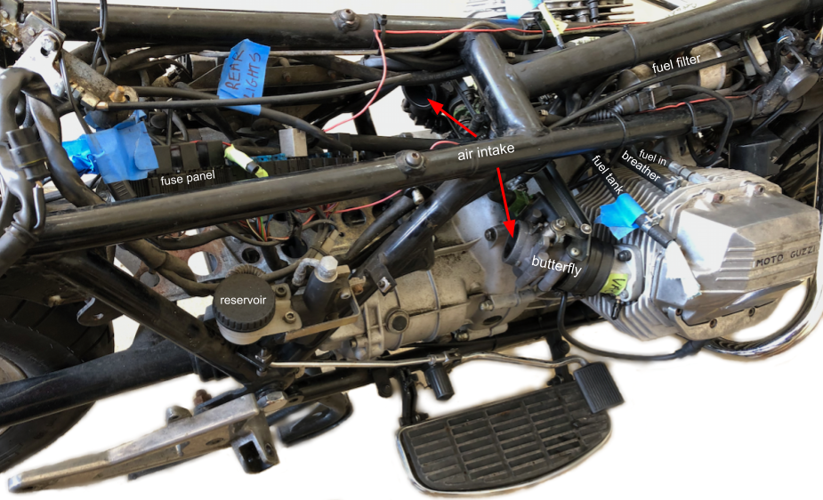
Remaining components after airbox and exhaust removal
After the airbox and exhaust removal, the throttle body assembly — cold start and throttle control cables as well as the intake butterfly housing — is revealed.
Gear shifter

Like nearly all motorcycles, the Moto Guzzi California shifts gears using a left foot assembly operated in coordination with a left hand clutch lever. Six different linkages move the sequential gearbox through all the gears and a neutral position.
For first gear, the foot lever is pressed all the way down with the toe. Neutral is between 1st and 2nd gears. Higher gears are reached by successive heel down clicks.
Unlike many shift cars that have a central neutral position, the motorcycle’s sequential system means that, for example, to go from 5th to 2nd gear in a downshift, the rider must pass through 4th and then 3rd gear in order.
The neural position is indicated by a green indicator light on the dash, and this feature will also be incorporated in the cyclecar dash design.
A new linkage arrangement will obviously be required to move gear selection from a foot lever to a traditional tunnel shifter control setup.
Engine-to-chassis electrical
To prepare the engine for removal, all electrical connections between the engine and the chassis frame must be disconnected:
- optional oil pressure transmitter and oil temperature sensor including ground wires
- oil pressure switch
- crankshaft (timing) position sensor
- starter motor assembly and wire connections
- gearbox neutral switch (behind the starter motor)
- alternator to voltage regulator mounted on frame
- spark plug cables (pull off plug terminal)
- voltage regulator ground wire (if not previously removed)
Optional oil pressure and temperature

Optional oil temperature (L) and pressure (R) sensors
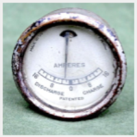
Our Moto Guzzi was outfitted with an optional 4-way gauge to read oil temperature and pressure, fuel level, and voltage.
Located at the rear of the oil pan and in a second spacer is the optional temperature sensor — on the left side in lieu of the regular fill plug — and the pressure transmitter — on the right side in an additional spacer. The pressure transmitter has two leads; one is for a nearby chassis ground. We may not retain these optional gauge inputs; a new fill plug can be easily fitted, and the additional spacer removed entirely. In fact, there may not be enough room for the second spacer in our cyclecar chassis.
Oil pressure switch
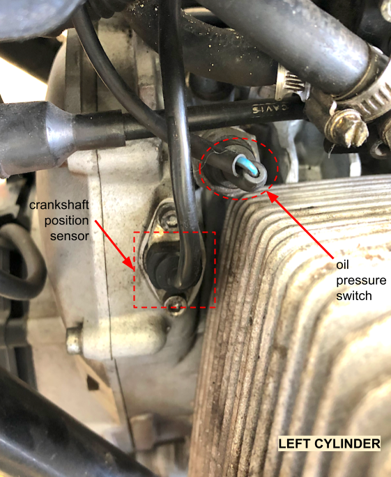
Oil pressure and position sensor
The oil pressure switch drives the dash low oil pressure warning indicator and is located on the top of the engine block towards the front.
This switch is directly connected with a blue/black wire on the low pressure indicator bulb negative terminal. When the switch is triggered by excessively low oil pressure, it completes a ground and the indicator light then illuminates.
Crankshaft position sensor
The crankshaft position sensor is located next to the oil pressure switch on the left side of the engine block.
Starter motor
Two bolts hold the starter motor to the engine block. Label all the terminal leads that are attached to the one large threaded stud and small tab.

Starter motor connections and gearbox neutral switch
Neutral switch
The gearbox neutral switch is located directly behind the starter motor.
Alternator to voltage regulator
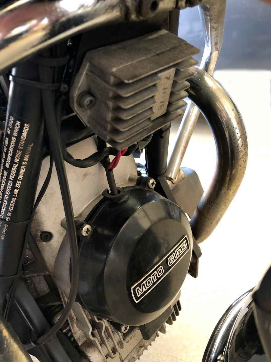
Alternator and voltage regulator
The alternator at the front of the engine block has a pigtail that protrudes from the top of the casing and connects directly to the voltage regulator mounted above the alternator on the frame.
The alternator usually has a plug to keep the leads straight, but for some reason our voltage regulator was spiced in without the plug. This is probably because our regulator is a relatively recent addition (2018) and probably didn’t have the correct connector. We just cut the wires for now, but noted their correct position.
The stock alternator cover is black plastic with a “Moto Guzzi” label on the front. Since this part of the engine will be prominently displayed in the cyclecar, we well replace the cover with a chrome one that was featured on the California “anniversary” edition.
Clutch cable
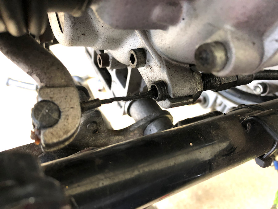
Clutch cable
The clutch cable, operated by the left hand lever, connects to the gearbox on the right side near the bottom frame rail.
To remove, first loosen the cable at the hand lever, and then unscrew the threaded hollow positioning spacer.
When the spacer is out, the cable can be passed through a small slit in the clutch mount.
Speedometer cable

Speedometer cable
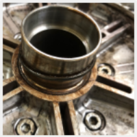
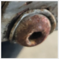
The speedometer cable runs from the gauge drive to a terminus at the end of the engine block.
Unscrew the knurled knob to remove the cable.
The hex nut fitting holds a geared shaft that determines vehicle speed based on the rotating rear wheel. Thus, any change to the standard rear wheel diameter will have an impact on the accuracy of speed readings.
Front frame guard
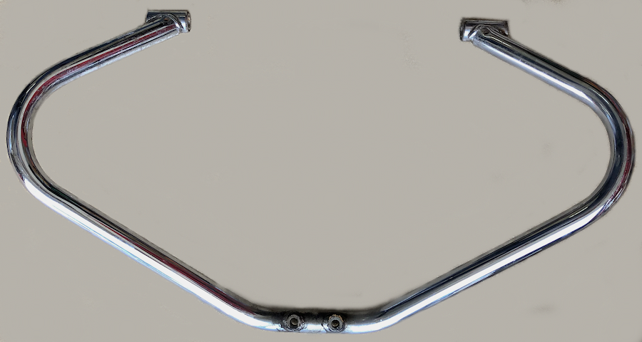
Front frame guard
The front frame guard — a large U-shape (part GU30450260) — crosses over both cylinder heads. Remove the two bolts holding the guard to the top of the frame and then pry off the bottom end caps to reveal a M12 x 20 bolt that passes through the frame. Carefully unfasten these bolts on both sides and remove the guard.
Breather hoses

Dual breather hoses attached to frame
Dual breather hoses run from each cylinder to small nipples on the frame. Remove each hose from both the frame and the cylinder head.
Remove the large S-shaped breather hose attached to the back of engine block.
These hoses will not be reused since the cyclecar will require a complete redesign of the engine breathing system.