Topics
Overview
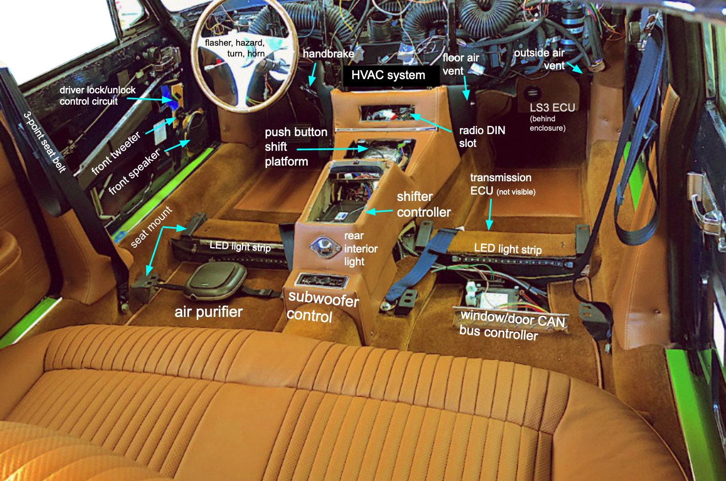
The Dakota Digital HDX electronic gauge encompasses virtually all vehicle information into a single display. The system links to the LS3 ECU via CAN bus using a BIM-02-01 interface module. The unit is fully programmable and flexible, so we have incorporated a number of custom features.
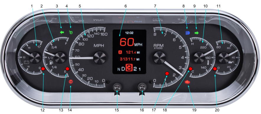
- voltmeter
- fuel level
- left turn indicator (warning if active over 3/4 mile)
- backlight demist indicator (repurposed cruise control symbol)
- speedometer
- TFT information screen (see details below)
- tachometer
- high beam indicator
- right turn indicator (warning if active over 3/4 mile)
- water temperature
- oil pressure
- low voltage warning
- low fuel warning
- handbrake on/brake fluid low warning
- left touch switch
- right touch switch
- tachometer RPM warning
- high temperature warning
- check engine (MIL) warning
- low oil pressure warning
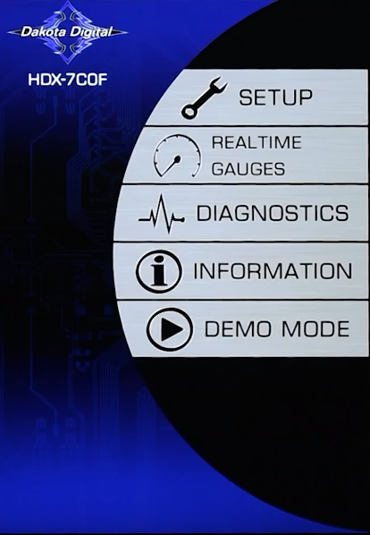
TFT information screen

Default home screen left, customized version on right
The center TFT display (see item 6 above) opens with a fixed home screen. Our implementation will omit the optional compass direction and outside air temperature data (this requires an additional Dakota Digital module and has low utility given data readily available in our navigation system) as well as the gear position indicator.
While CAN bus data typically collected by the BIM-02-1 module includes gear position, the General Motors specification for the Connect ‘n Cruise LS3 crate engine and 4L65E automatic transmission omits this part of the dataset. Dakota Digital’s BIM anticipates gear position in GM’s proprietary CAN bus data format will be transmitted, but none is actually received. The default error for lack of data is to just display “N” (neutral); as a result, the HDX gear position display always shows “N” regardless of the actual gear selected — rather irritating!
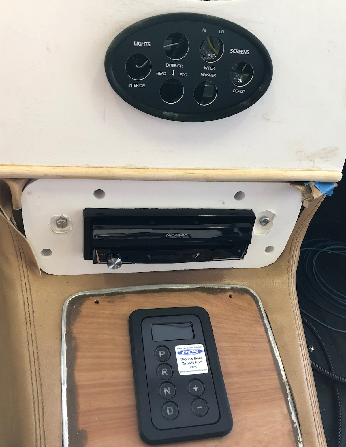
In fact, gear position on the TFT screen is redundant since the GSM keypad on the center console always displays the highlighted gear selection anyway. Fortunately, the BIM-derived gear data on the HDX can be turned off. However this requires functionality only in software version 1.8 or higher. Our BIM unit did have not the latest software, but Dakota Digital upgraded us for no additional cost.
Group screens

In addition to the fixed home screen, the TFT displays up to 5 different group data screens (A through E), all programmable. Data is organized into four layers — 1 to 4, top to bottom — for each group so this provides a great deal of flexibility.
Beyond operating data presentation, the layers are used to display specific message and gauge data alerts generated by various switches and settings in the HDX control box.
GROUP DATASETS
| A | B | C | D | E |
|---|---|---|---|---|
| range to empty | volts | 0-60 time | trans temp | clock |
| trip A | fuel level | high speed | air temp | timer |
| trip B | water temp | 1/4 mile | intake temp | tach bar |
| service due | oil pressure | 1/8 mile | high RPM | tach digital |
Message alerts
The default HDX settings provide several system and four programmable text message switches (“wait to start”, “4×4”, and two unassigned extras) that we have repurposed by substituting our own text; the HDX iPhone bluetooth app makes this a straightforward task. Two of the programmable switches are ground activated, while two require positive 12 volts. WARN message types are displayed in red.
TFT PROGRAMMABLE ALERT MESSAGES
| Terminal | Switch | Message | Type | Purpose or activation |
|---|---|---|---|---|
| EXTRA | ground | DR OPEN | WARN | door not closed completely |
| EXTRA | +12v | SET NEX | INFO | Pioneer audio setup toggle switch is on |
| 4x4 | ground | FAN ON | INFO | 2nd fan on due to water/refrigerant temperature |
| WAIT | +12v | PURIFY | INFO | air purifier on (fan speed set on unit) |
A service counter under the speedometer setup uses increments of 500 miles and conveniently reminds about oil changes and other maintenance tasks with a SERVICE DUE message. If the exterior light switch is pressed three times, the automatic dimming features will be disabled with a DIM DISABLED message. Other system messages cover sensor faults and data setup instructions.
TFT HDX SYSTEM ALERT MESSAGES
| System message | Error type or activation |
|---|---|
| SERVICE DUE | programmable service countdown meter reaches zero |
| PLEASE CALIBRATE SPEED | speedometer setup required |
| WATER SHORTED | temperature sensor short or out-of-range error |
| WATER OPEN | temperature sensor disconnected or out-of-range error |
| OIL FAIL HIGH | pressure sensor short or out-of-range error |
| OIL FAIL LOW | pressure sensor disconnected or out-of-range error |
| FUEL SHORTED | sender short or out-of-range error |
| FUEL OPEN | sender disconnected or out-of-range error |
| DIM DISABLED | headlight switch on/off 3 times to stop dimming |
| HOLD TO CLR | touch switch to clear message |
| CANNOT CLEAR | data or message cannot be erased |
| HOLD TO SET | touch switch to enter data |
| RELEASE | release switch to save data |
| ENTER SETUP | touch both HDX switches |
We have elected to broadcast all text messages on the bottom of the TFT screen (level 4). When gauges exceed warning level thresholds, a red LED is activated and gauge data is displayed at the top of the TFT screen (level 1). Most gauge data and messages can be cleared by touching either HXD switch (see 15 or 16 above).
Gauge LED warnings
Five gauges — voltmeter, fuel level, tachometer, water temperature, and oil pressure — have embedded red LED warning lights that are activated when certain threshold values are reached (see 12, 13, 17, 18, 20 above). The fuel level is factory preset at 10% of tank capacity while the other gauges can be programmed for specific warning thresholds.
- voltmeter: BELOW 12.4v — <75% charge and vulnerable to sulfation
- voltmeter: ABOVE 17.5v — excessive recharging
- fuel level: 10% — percent of tank capacity (factory preset)
- water temperature: 210°F — triggers second cooling fan (see also HVAC)
- oil pressure: 24 PSI — LS3 specification for hot low pressure minimum
- tachometer: 5900 RPM — LS3 maximum horsepower output
Programming
HDX iPhone programming app
The elegant HDX compendium of vehicle data becomes, given its many options, rather complicated to program. A text-based setup TFT display is reached by touching the two HDX switch at the same time; scrolling and data entry is also achieved with the touch switches.
An alternative graphic programming method, the HDX bluetooth-connected iPhone app, provides some added functionality with real time setting and data changes so it can be conveniently used some distance away from the dash area (pressing the HDX touch switches on the dash can also get a little tedious).
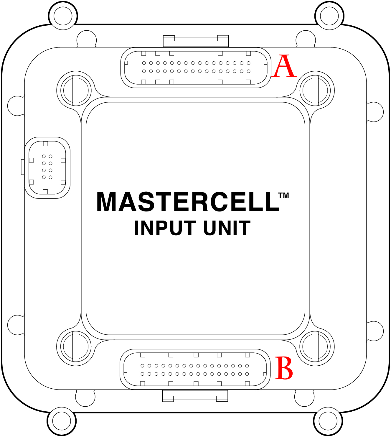
HDX wiring

Yellow highlighted boxes indicate customization or re-purposing of default functions. The ENGINE terminal triggers a “check engine” warning but the BIM module communicates directly from the LS3 ECU so this terminal does not need to be connected. Speedometer and tachometer functions are also handled by CAN bus data via the BIM module. As discussed above, the gear display has been disabled.