Topics
Background
Climate control refers to automotive integrated heating, ventilation and air conditioning system (also called automotive HVAC).
Modern electric air conditioning was pioneered in 1902 by Willis Haviland Carrier, a New York engineer who was the first to understand the dynamics of humidity control.

Weather Eye system in the Nash Ambassador
Building air conditioning system components were then adapted for automotive use by Bishop and Babcock Co. in Ohio; their “Bishop and Babcock Weather Conditioner”, promoted by Packard in 1939, proved too expensive for its dubious performance, but the innovative idea of managing the air inside the car’s cabin was pursued by Cadillac and Chrysler in the early 1940s.
The 1953 Chrysler Imperial introduced Airtemp, the first automotive system with single switch control.
But it was the 1954 Nash Ambassador that offered the first fully integrated heating, ventilating, and air conditioning system marketed as the “Weather Eye”.
Jaguar lagged behind the American car companies by at least a decade, displaying an ambiguous attitude towards the American pursuit of comfort and convenience. Not surprisingly, Jaguar’s engineering effort was both confusing and largely ineffectual. Several experiments and third-party components provided half-hearted optional retrofits in 1960s Jaguars. Customers routinely complained.
1972 HVAC partial integration
By the 1972 model year the HVAC concept finally jelled in the sense that Jaguar at least described it in the official XJ6 Service Manual (publication E-155) as a “factory-installed optional extra … fitted in conjunction with the car heating and ventilating system standard on all cars.”

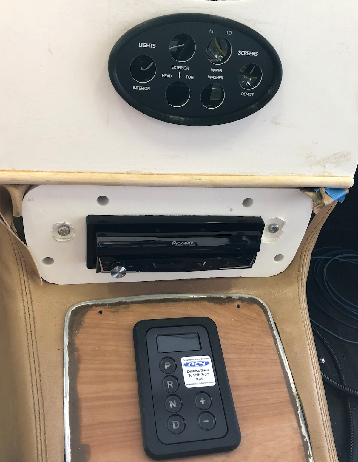
Delanair Mark II control panel
Jaguar cobbled together a reasonably sophisticated “system” (in theory at least) built around a General Motors Frigidair compressor and other keys parts from an obscure U.K. firm named Delaney Galley. Galley’s heritage was radiators (planes and autos) so expansion into heat exchangers was a natural path.
In fact, Galley was the first U.K. company to design an air conditioning system for U.K. automobiles. Their product was known as “Delanair”, an unoriginal contraction of “Delaney” and “air conditioning”, and the Mark II model (not to be confused with the Jaguar Mk2 saloon) was installed in most 1970-87 Jaguars.

1972 Jaguar Delanair info card
Needless to say, these early A/C systems struggled with proper air flow, temperature control, and reliability. Still, the Delanair Mark II in our 1972 XJ6 has a true climate control design in that heat and A/C share an integrated panel and air flow vents.
Well, the system isn’t fully integrated — the XJ6 delivers “an additional fresh air supply” through front wing ducts and louvers that draw from grilles in the headlamp embellishers! Our retrofit will have to determine how to overcome the Delanair shortcomings.
Several engine-mounted components like the compressor, water pump, and alternator will be replaced (in concert with the General Motors LSx swap) as well as the overall plumbing layout.
How climate control works
Modern climate control combines two separate, but parallel, systems: one generates cold air while the other generates hot air in evaporator and heater cores respectively that are then combined in a blower fan housing to distribute a controlled blend of air in the cabin.

There are a number of ways the cold and hot air generation can be combined, but the basic principle is the same: outside and recycled air is passed through a cooling evaporator to a heater core and then blended through a series of flaps and channels.

Jaguar XJ6 airflow
Jaguar provided two pathways for air inflow into the XJ6 cabin: 1) through the center hood vent controlled by the HVAC system, and 2) via a small grille incorporated into the front headlight embellishers. The illustrations below show how the air enters the cabin.

Air intake through the front headlight embellishers
The effectiveness of the headlight airflow design is questionable (but obviously deemed to be a necessary workaround by Jaguar to supplement the center hood vent since it was introduced part way into XJ6 Series 1 production). Air enters the embellisher opening and then moves along under the wing through an air hose.
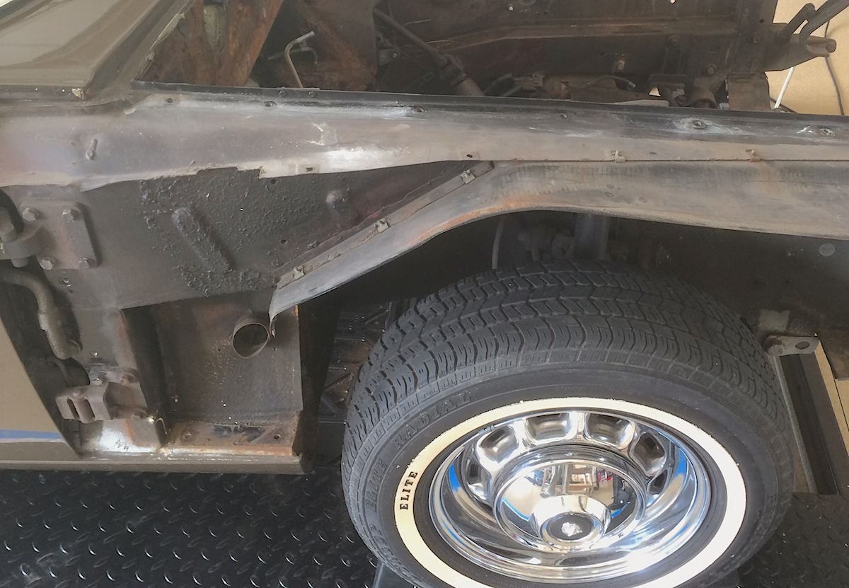
Wing removed showing air intake path (hose not shown)
The air hose connects near the bottom of the wing panel after first bending 45º down and then making a 90º turn to attach to the cylindrical fitting. Without a fan to drive the air, very little flow takes places unless the car is moving at high speed.

Air intake hose fitting near front tire
Inside the cabin on the opposite side of the chassis wall air hose fitting, a vent housing is bolted to the sheet metal wall that surrounds a complicated louver lever mechanism. What shows into the cabin is a cheap plastic round cover that protrudes from the top of the outer kick panel.

Louver cover on upper kick panel
A pull lever control opens and closes the louver (theoretically at least). Air flow is typically so low that opening and closing the vent has no noticeable impact.

Louver control lever
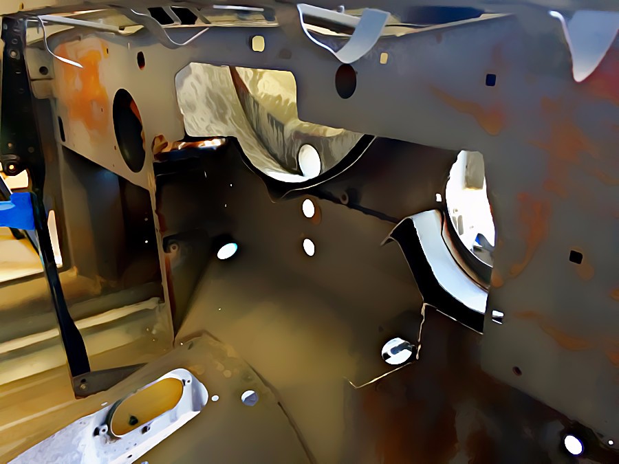
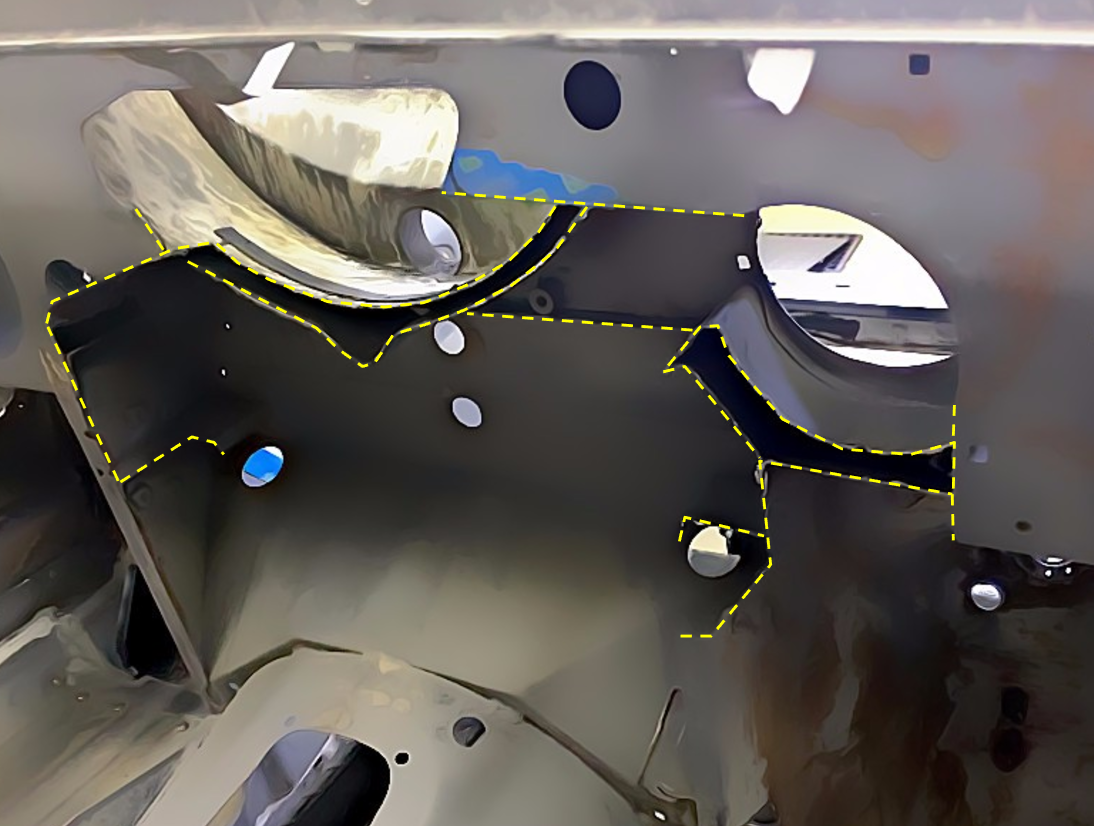
Air moves through the cabin to the rear backlight (window) shelf where a “top hat” opening allows air to pass into a tray-like “extractor”. The extractor has four rectangular openings into the boot that are covered by little corresponding metal flaps covered on the inside with foam.
Originally these flaps were attached with some kind of flexible material hinge. The hinges and foam degrade over time causing a “cow bell chime” condition when the metal flaps vibrate every time a door opens or a pothole jars the vehicle. Charming.

Air flows out through the backlight shelf into the extractor tray
HVAC modernization
All HVAC components need to match or balance each other in terms of capacity, power, output, fluids, pressure, and so on. The first planning hurdle, however, concerns the evaporator that must somehow be squeezed in behind the dash. There are two basic options: 1) refurbish the existing Jaguar XJ6 evaporator, or 2) look to the aftermarket for a solution that can be made to fit.
As noted above, Jaguar’s 1972 HVAC system does not fully integrate the heater cooling cores; the heater core sits on a shelf outside the evaporator body and moisture drips down the support leg of the dash infrastructure as evidenced by rust damage above the transmission tunnel. In addition, the dual fan air flow duct system has bottlenecks which means that even with high power fans, the capacity of the system would be limited.
This antiquated Jaguar design is probably the reason why no one offers an upgrade to the XJ6 Series 1 AC system. RetroAir, one of the few companies to address the Jaguar HVAC system, only offers Series 3 component replacements, and even then the dreaded evaporator is left untouched. It seems, therefore, that any attempt to improve the original Jaguar system will fall far short of optimal performance compared to current technology.
Vintage Air
Vintage Air, founded in 1976 to serve the street rod and custom performance, offers a sophisticated product line and their evaporators give us the best chance of finding a unit that will fit.
It’s important to note that the Vintage Air HVAC system only uses recirculated air — meaning the XJ6 center hood vent must be blocked off or modified; some kind of fresh air intake apart from the side windows seems like a good idea.
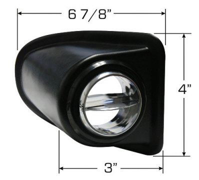
Vintage Air kick panel louver
The original complicated (and shoddy) lever/louver could be replaced by a simple kick panel louver. In very cold or hot weather this could be closed manually by reaching down (a little inconvenient) under the dash.
But in most conditions, the vent could simply be left open to draw in a little outside air.
In any event, the extractor tray discussed above must be repaired to fix the little rectangular vent flap hinges and pad the inside surface to eliminate any quaint “cow bells”.
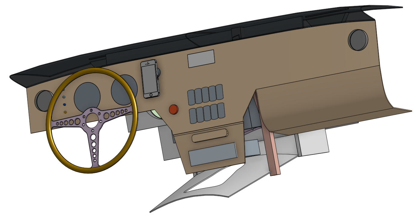
Dash infrastructure
The first task is to accurately model the metal structure to see what the space limitations are and how they might be modified.
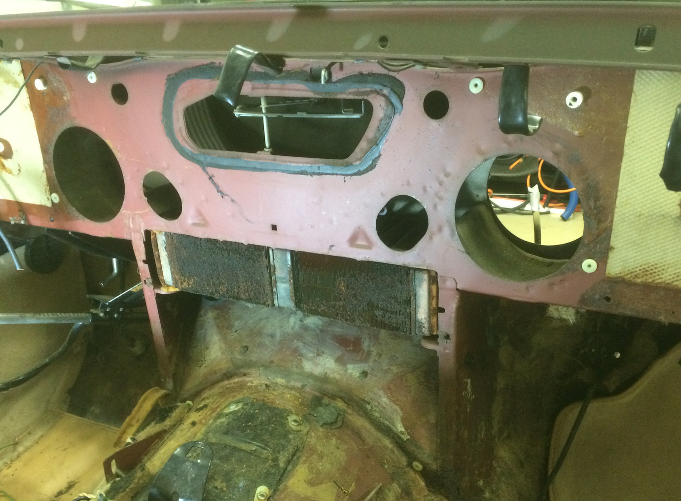
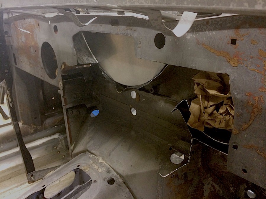
Metal infrastructure after removal of evaporator
After removal of the dash facia and the original evaporator, the metal skeleton of the dash infrastructure is exposed.
The old heater core is tucked into a shelf and the two large circle cutouts on either side housed the twin fans.
The other odd cutouts were for ducts and various connections. No parts from the old system will be reused.

The little scoops on the top are for the wipers; the windscreen sits about halfway between the end of the wiper scoops and the trailing edge of the front air vent (that extends beyond the firewall).
Vintage Air evaporator models
After looking at the full range of Vintage Air evaporators, the two smaller units — called the Gen II ComPac and the Gen II Mini — are the best candidates. A 3D rendering of each model was developed using available top and side drawings, but these are rough estimates only.
The Gen II Mini is the smallest available evaporator, but the hose connections are at the bottom of the unit which means that plumbing will probably need to routed up towards the top of the dash (thus using up valuable space).
3D rendering of VintageAir Gen II Mini evaporator
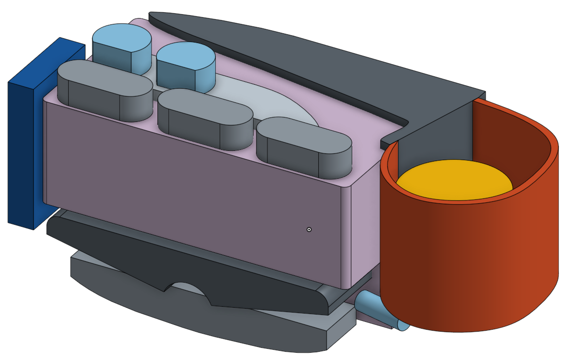
The Gen II ComPac is about 1.5″ longer but provides connections at the top of the unit.

3D rendering of VintageAir Gen II ComPac evaporator
The approximate placement of the Vintage Air Gen II ComPac shows the obvious conflicts with the metal structure, most dramatically on the right side (and the Mini is about the same).


Cutouts will be needed along the front metal plate with enough room for 2-inch hoses that connect the defrost and AC vents to the outlets on the top of the unit. Once the evaporator is positioned, the virtual dash helps to check for others conflicts.

Test fit confirmation
Getting the evaporator to fit is obviously a major issue in any HVAC conversion, and VintageAir is well aware of this given their experience in the custom build community. To help the install process, they have developed a plastic 3D printer version of the evaporator for test fitting. Order one, test the fit, and then order the real system and they credit you back for the cost of the plastic model.

Test fit of the plastic Vintage Air Gen II ComPac model
Test fitting the plastic model in the car and against our 3D CAD drawings validates that the Gen II ComPac will fit with some dash sheet metal modification.
Dash sheet metal cutouts required to fit the HVAC unit
Removing a section of the sheet metal dash infrastructure was done with a cut-off wheel and plasma cutter.
Cutaway lines show removal of dash section for HVAC fitment
The HVAC unit will attach with two front brackets fixed to the vertical dash supports plus two in the rear: one will be bolted to the vent blocking plate and the other will be on the lower right side.

Vintage Air plastic model shown with front vertical dash supports in red outline
The passenger side bracket became rather elaborate since it also provides added stiffness to the horizontal dash and vertical elements that connect to the transmission tunnel. Since part of the dash infrastructure was cut away, compensating with a specially designed support makes sense.
A further complication is that this bracket must be removable; it can only be installed after the HVAC unit is in. Bolts are used on the vertical face, but nutserts are required at the top because there is no access point.

Passenger side HVAC bracket and dash reinforcement brace
Hood vent

Center hood vent
The XJ6 continues the Jaguar saloon tradition of a center vent that feeds fresh air into the cabin. Water that enters the vent flows to the bottom out a drain pipe right above the tunnel entrance.
Unfortunately, this design conflicts with the Vintage Air system that only uses recirculated air, although fresh air may enter from somewhere else that is not part of the HVAC unit. Therefore, the vent will need to blocked so that water cannot enter the cabin while fresh airflow is eliminated entirely.

Vent opening showing firewall (red line)
A simple U-shaped plate works well. The blocking plate is attached at the top under the trailing lip of the vent surround. The notch in the curved section rests against the bottom sheet metal support.
Vent blocking plate with screws holes along the top
Cabin side view of vent blocking plate
One advantage of the blocking plate is that it provides a good rear mounting surface for the HVAC unit.


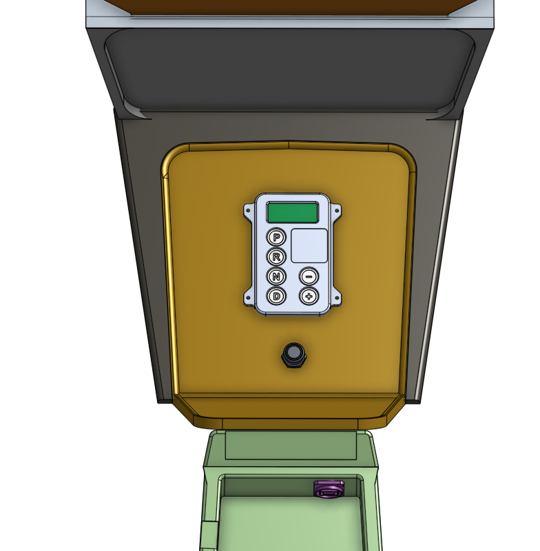


I just love your 3D illustrations.