Topics
Overview
General Motors does not excel in product documentation, and one notable information desert concerns fuel flow; that is, how gasoline gets from the tank to the fuel injectors. The closest Chevrolet application of our LS3 6.2L crate engine is the 2010-13 Corvette. As a starting point, let’s see how the Corvette fuel delivery works.
Corvette evolution
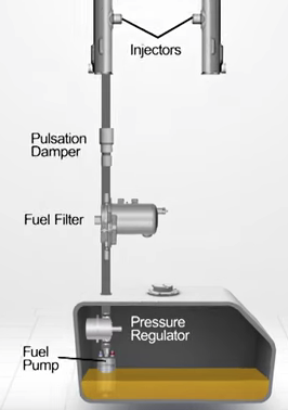
The Corvette fuel flow is “returnless” in that there is only a single line running along the undercarriage from the pump to the fuel rails and injectors. Earlier Corvettes deployed a combined filter and regulator to clean the gasoline, maintain pressure, and also return unused gasoline back into the tank. So this pre-2010 system is really semi-returnless; there is a return line but it doesn’t carry much volume. The pure returnless system in today’s Corvettes places the filter/regulator in the tank, and thus there is literally no return.
The first returnless fuel layout was introduced on 1993 Chrysler V6 and V8 truck engines and then extended to all Chrysler vehicles by 1998. Toyota introduced its first returnless system in 1996, followed by General Motors and Ford in 1999 who rushed to meet EPA emission deadlines; today nearly all new vehicles feature returnless EFI architecture.
Returnless fuel delivery system
The primary reason General Motors adopted returnless flow was to reduce the temperature of gasoline circulating in the lines. Fuel absorbs heat in the engine bay, and temperature causes more vapor emissions and waste. Thus, the returnless design motivation was not necessarily to save money by eliminating a second line, nor was it to boost performance. Returnless systems are generally less polluting and result in slightly better gas mileage. Government EPA regulations provided the corporate motivation.
Returnless designs do keep overall gasoline temperatures lower, especially in the tank since no (or limited) heated fuel re-enters through a return port. However, gasoline in the fuel rails tends to run hotter since there is no recirculating return line. To compensate, returnless systems generally operate at higher pressure to minimize vapor lock and emission problems.
Pressure escalation
At the end of the C3 Corvette models in 1981, GM introduced a new Crossfire Throttle Body Injection, literally a fusion between a carburetor and fuel injected design, that initially set fuel pressure at 9-13 PSI. Within a year, this was raised to 14 PSI to eliminate fuel starvation, especially at higher RPMs.
The 1985 C4 Corvette launched Tuned Port Injection (TPI), a more efficient induction fuel delivery, with a pressure specification of 36 to 39 PSI (47 to 48 PSI if the vacuum hose was disconnected). For the 1988 to 1996 C4 corvettes with returnless layouts, the stock fuel pressure became 40 to 42 PSI, an escalation to minimize various fuel starvation and shortcomings.
Pressure regulation

Linked computers regulate pressure
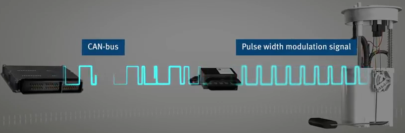
The Corvette returnless architecture relies on a special pump module to regulate fuel delivery. A fuel pressure sensor mounted on the fuel rail monitor pressure. When pressure drops as engine load or speed increase, the main engine computer (ECU) compensates by increasing injector duration (on time) and/or communicates with the pump control unit to change the speed of the fuel pump. Basically these linked computers always maintain a constant pressure.
CAN bus – PWM communication
The main engine computer transmits CAN bus 5-volt signals to the fuel module. In turn, the fuel module outputs pulse width modulation (PWM) to control pump speed.
PWM control is essentially like turning a rotary dial up and down.
Comparison to aftermarket solutions

OEM in-tank modulal components
OEM fuel delivery now involves complex proprietary components that work together in a closed system. This is quite different from the older on/off simple switching current method of pump control that could incorporate many different pumps, regulators, filters, and fuel level sending units. These functions are now bundled together into a single in-tank unit.
GM made the decision, not surprisingly, to keep their aftermarket offerings like the LS3 Connect & Cruise package as simple as possible. Thus, there is no fuel control module included, and the ECU only outputs the “old school” on/off pulse to the pump.
As a result, designing a fuel delivery system for the crate LS3 requires a stand-alone pressure regulator as well as an external filter and separate sending unit.
System design
The LS3 engine, as a widely adopted platform, sports an endless variety of mods to the stock configuration.
Non-return configuration
The stock fuel rail configuration is returnless, the heritage from the 2010-13 Corvette discussed above. However, without the proprietary CAN bus and PWM fuel control and in-tank module, some non-OEM modifications are essential.
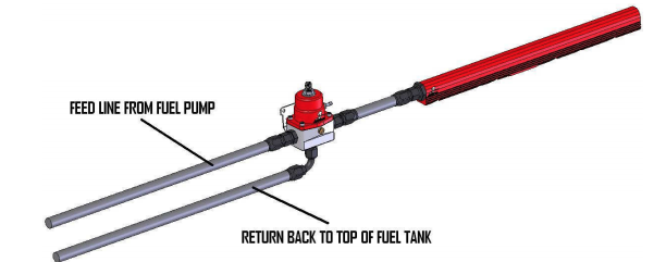
Option one is to retain the returnless fuel rail design. The advantage is the elimination of a second fuel line return as well as the convenience of mounting the regulator next to the fuel tank in the trunk, away from the grime and heat of the engine bay. A disadvantage is that hot fuel returns partly on the same line and performance may not be optimized.
Dual return line setup
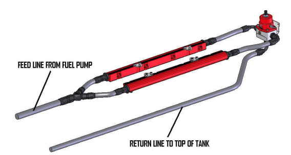
Option two is to deploy a full return line setup that requires the replacement of the OEM LS3 fuel rails and adds connections, including a tee to split the incoming line out to the dual fuel rails. The pressure regulator in this arrangement must be mounted close the fuel rails. Fuel temperatures may be somewhat lower, but in our non-racing application, this is of doubtful utility.
So we’ll retain the original returnless pattern.
Fuel filters
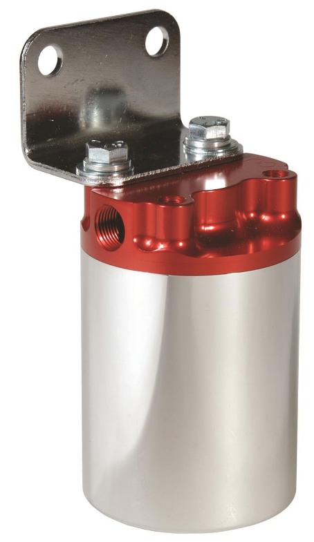
Aeromotive 12308 canister 10 micron filter
Our in-tank Aeromotive 340 Stealth pump includes a “sock” pre-pump filter, but we still need an external post-pump filter.
Aeromotive recommends a 10 micron filter between the fuel pump and the pressure regulator. One convenient place for the filter is in the back of the prior tire hold, away from the heat of the engine bay or the grime of the undercarriage. Fortunately, the Aeromotive 12308 canister style 10 micron filter fits nicely.
Since we’re also placing the Aeromotive 13109 pressure regulator in the trunk, the canister filter location will minimize fuel line lengths.
Pressure regulator
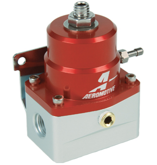
Aeromotive 13109 bypass regulator
The Aeromotive 13109 is a bypass regulator which means it has a three-way flow pattern. The top side inlet/outlet ports provide a pressure-regulated flow through of fuel, while a bottom outlet port “bypasses” unused fuel to the tank’s return inlet. The regulator will be fitted with an optional pressure gauge. When mounted on the rear trunk wall (opposite side of the rear seats), pressure can be quickly checked with the trunk lid open.
Component layout
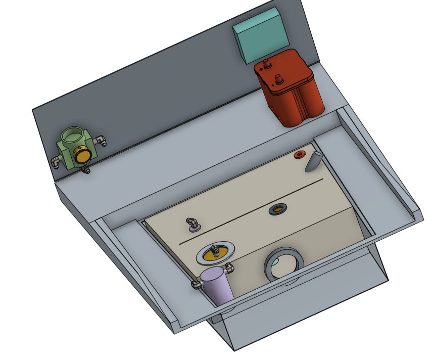
Trunk placement of components
The fuel tank and EFI components share trunk space with the battery and rear wiring fuses (and perhaps an audio subwoofer!). Most of the components can be hidden by a horizontal panel across the spare tire hold and an vertical one blocking off the rear trunk shelf.
The fuel flow moves from the pump to the 10 micron canister filter to the pressure regulator (all in the trunk), and then on to the sole input on the fuel rail. Since this is a returnless design, there is no return line from the fuel rails. Instead the bypass regulator acts as the tee split for the return line as illustrated below.