Topics
Overview
For most LS engine swaps, the engine mount issue is a minor one because so many aftermarket solutions exist for virtually all American muscle and sport cars. Alas, the British Jaguar hasn’t received the same aftermarket attention since LS swaps are relatively rare.
Therefore, the problem of how to mount the LS block on the XJ6 frame must be designed from scratch. Well, not exactly from scratch, since Chevy small block engines have been swapped into the XJ6 for many years, and we can at least borrow the basic configuration from those efforts.

SunCoast Conversions style pedestal mount
The pioneer of Chevy V8 small block-to-Jaguar XJ engine swaps is Jim Johnson of SunCoast Conversions. Jim developed a 45-degree pedestal base that mounts directly on the Jaguar XJ6 front suspension crossmember. This simple design comfortably accommodates the older style Gen I and Gen II SBC V8s.
Adaptation for LSx blocks
The Gen III/IV LS mounting bolt holes are located farther back (towards the bell housing) than the earlier SBC models, so a “slider” adapter is required if the same crossmember support position must be retained (and there isn’t an obvious alternative on the XJ6 frame).
Fortunately, this backward slide is a common one for any SBC-to-LS swap and has been well addressed by the aftermarket. Many alternatives exist, from simple flat plates that offer a single relocated fixed position to more elaborate designs that offer back-and-forth flexibility. We may need the flexibility to clear the exhaust headers and mate up precisely with the transmission crossmember and propeller shaft.
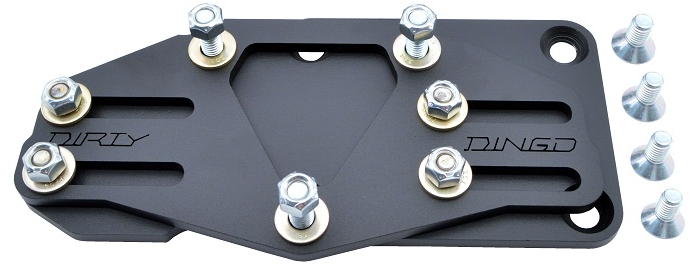
Dirty Dingo SBC-to-LS block sliding adapter
Dirty Dingo Motorsports offers an elegant slotted slider that moves the engine block up to 2″ forward from the standard LS position and also raises the block about 1/4″ above the standard SBC position. This additional 1/4″ may help us clear the steering rack and establish a more level sight line for an over-the-radiator air intake installation.

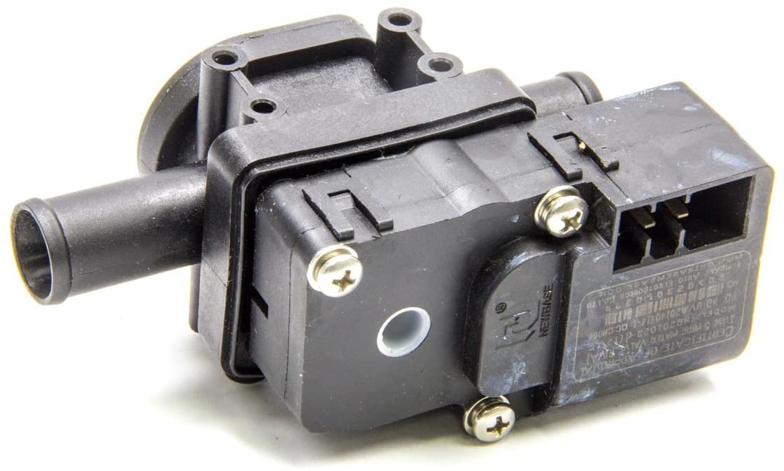
Energy Suspension’s 3-bolt poly mount
The Dingo slider (model SKU is DD-Slider) accepts any standard 3-bolt Chevy vibration isolator, or the traditional “clam shell” design.
Original GM vibration isolators are difficult to find, but high quality aftermarket ones are readily available, like Energy Suspension’s polyurethane upgrades. These come in red or black poly (there is no performance difference between the colors; black just has some added graphite!) in either zinc gold or chrome finish.
Conceptually, the complete mounting system has three components that all must work together: 1) the SBC-to-LS slider adapter (salmon color in the drawing), 2) the vibration isolator (shown in drawing without its pre-load back plate that is not necessary with the slider adapter plate), and 3) the 45-degree pedestal support.

Complete mounting system with slider adapter, vibration interface, and pedestal support
The drawing below shows how the mounting system supports the engine block in the XJ6 engine bay.

Mounting system showing engine block and front crossmember
Initial fitment
The first test fitment of the LS3 in the engine bay confirms (thankfully!) that there are no serious conflicts. Note that the stock exhaust manifolds have been removed since a rear dump pattern interferes with the steering shaft on the driver’s side.
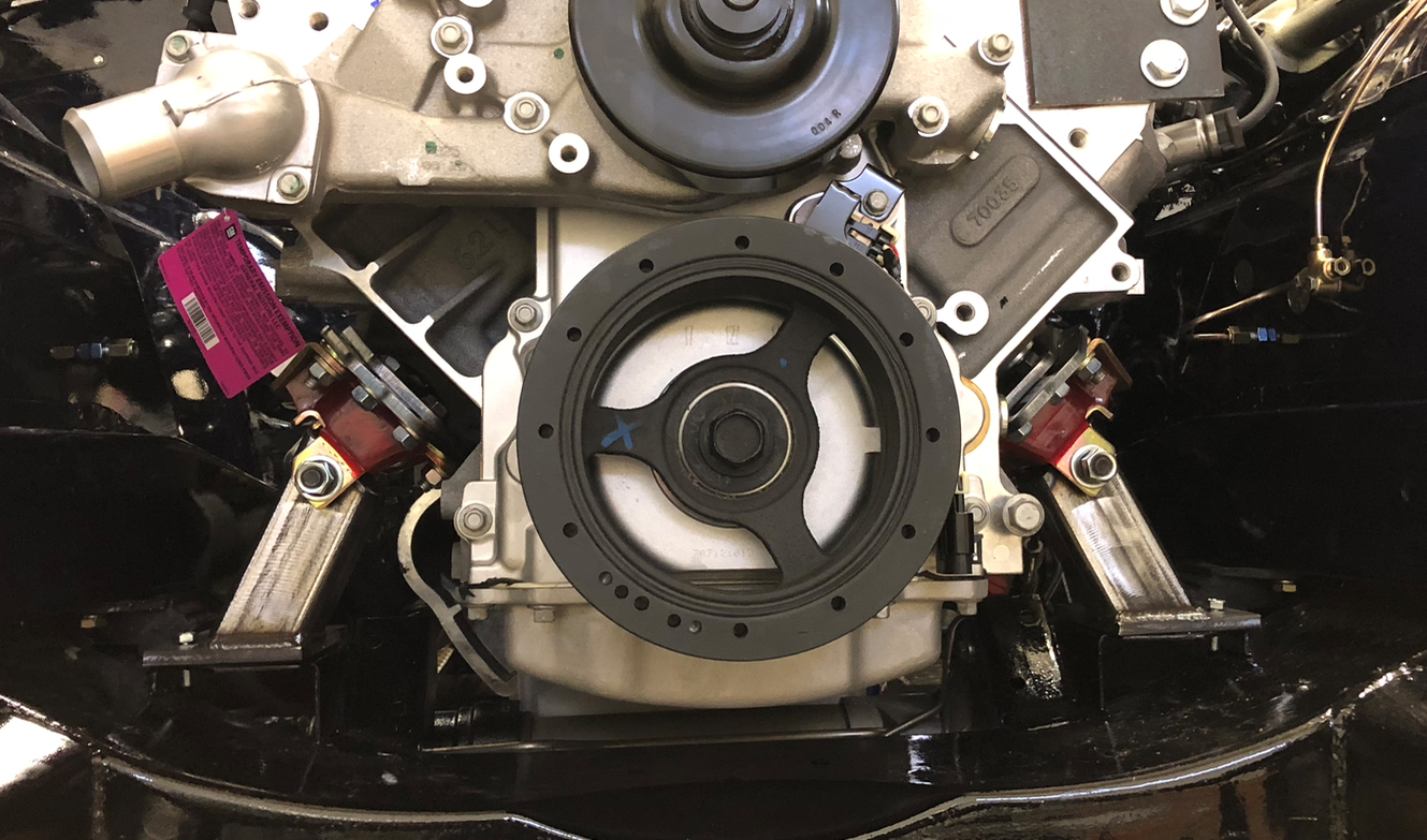
First firment of the LS3 in the engine bay (without exhaust manifolds)
Engine attitude problem
The first mount design resulted in the oil pan resting about one inch above the steering rack (the lowest point of contact). While this position easily cleared the top hood and provided sufficient room for the front accessories, we noticed that the engine exhibited a 3 degree pitch up and consequently the vertical surface on the transmission was pointed down 3 degrees. The face plate on the rear differential is exactly perpendicular to the ground (that is, a zero degree pitch).

Engine mount pitch of 3 degrees doesn’t match differential
Some geometry indicates how much the engine must be lowered, or the transmission end raised, to eliminate the pitch:
sin(3 degrees) x distance from engine to transmission mount = 0.052 x 40 = 2 inches
Revised mount design
In response to the engine pitch problem, we redesigned the pedestal mounts by shortening them 0.75″ and moving them forward towards the engine block.

Modified engine mounts to lower block about 3/4″
We also moved the pedestal location to the middle of the mounting plate and changed the bolt pattern to take advantage of four existing bolt holes in the crossmember platform.
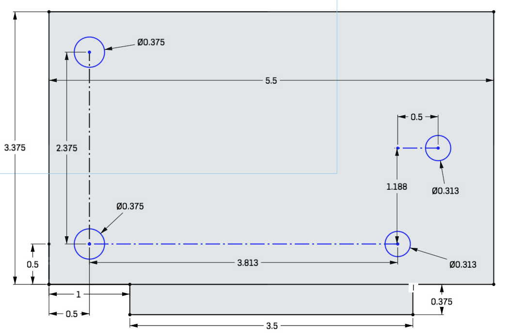
Mounting plate hole pattern
With the modified mounts, the engine now rests about 1/8″ above the steering rack, or about 3/4″ lower than previously. If this steering rack gap isn’t sufficient to handle normal engine vibration, we can easily shim the engine mounts up a little. The transmission rear mount was raised up as well.
The result is that the engine now has a minimal 1 degree pitch up. Hopefully this will not create any driveshaft vibration issue.


Looking good!
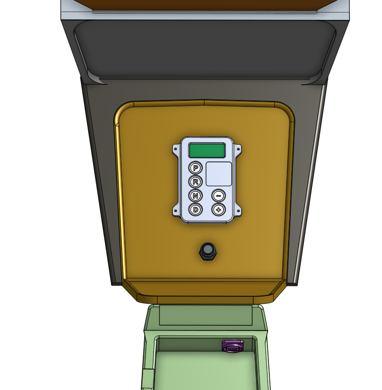
Hello, I am installing an LS2 / TR6060 into my 75 Jaguar XJ-C.
I was wondering if you sell or could make me some motor mounts? Thanks!
Zack, we don’t have any engine mount inventory and no plans to make any. The 1975 XJC may have slightly different requirements than our XJ6 model, but the basic design described above will work. Take careful measurements to any good machine shop and they should be able to fabricate two mounts for you.