Topics
System design
The Chevy LS3 V8 engine generates significant heat so a state-of-the-art cooling system must be part of restomod planning.
Major components
Pressurized cooling systems manufactured since the 1980s typically integrate seven major components:
- radiator (with or without fill cap)
- pressurized cap placed at highest point to enable air bubbles to rise
- cylinder cooling engine water jacket integrated with thermostat flow control propelled by serpentine belt-driven water pump (in cars with heaters, the water pump utilizes four openings where two small ports connect to the heater core)
- air bleed like the steam pipes used on the Chevy LS3
- electric cooling fan(s)
- remote pressurized recovery (surge) tank
- overflow tank (optional for street vehicles but required for many sanctioned races)
Pressurized cap
Most pressurized systems run at 16 psi (higher for extreme horsepower race applications). Higher pressure raises the boiling point of coolant and helps reduce steam that impacts cooling efficiency.
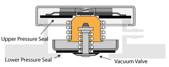
Despite its simple appearance, the cap performs three critical functions. At room temperature, the spring-loaded value is seated against the low pressure seal to prevent coolant from flowing up into the overflow outlet and tank. At engine operating temperature, the value opens and coolant flows into the overflow tank. As temperatures drop (like when the engine is shut off), the vacuum value opens and air (if no overflow tank) or coolant is sucked back in from the overflow tank.
System flow
There are three basic ways to set up the cooling flow: [1] use the 1994-2013 C5/C6 Corvette style with “direct fit” aftermarket components, [2] mimic the current 2016+ C7 Corvette/Camaro setup with current GM OEM parts, or [3] fashion a modified version that follows the Corvette layout using “universal” aftermarket components. (So-called “universal” parts are supposed to be easy to adapt to many vehicles, but some builders quip that they fit nothing in the Universe.)
All systems must deploy a recovery (surge) and overflow tank (optional depending on capacity and application) to mitigate the impact of thermal expansion of the coolant as engine operating temperatures rise.

Coolant is a 50/50 mix of water with other corrosion inhibitors/antifreeze chemicals like glycol and each ingredient has its own thermal expansion coefficient. The physics get a little complicated, but the bottom line is that coolant expands volumetrically about 4% as room temperature rises to engine operating temperature.
Thus, the LS3’s coolant capacity at room temperature of about 11.20 quarts expands to about 11.65, this 1/2 quart (14-16 oz) expansion must be handled adequately by the capacity of the recovery reservoir and, if needed, an additional overflow tank. Failure to handle this back-and-forth expansion/contraction of coolant results in overheating, loss of coolant, unwanted air pockets that cause hot spots, and other unpleasant problems.
Since recovery tanks generally are filled half way at room temperature, the expansion only capacity should be about 1/2 quart (implying a full capacity of one quart). Capacity over 1.5 quarts just takes up space in the engine bay. If the recovery tank alone holds less than one quart, a separate overflow may be needed.
C5/C6 Corvette style (1994-2013)
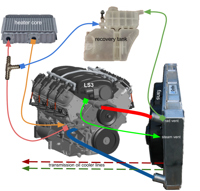
This configuration relies on a surge tank mated to a separate (optional) overflow tank.
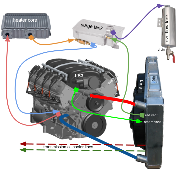
- DARK BLUE LINE: water pump draws coolant from lower passenger-side radiator port into LS engine block where coolant circulates through water jacket if threshold temperature reached, otherwise water pump bypass circuit recirculates coolant back through radiator (RED LINE)
- LIGHT GREEN LINE: LS steam tubes capture air pockets that migrate back to radiator port
- LIGHT RED LINE: coolant exits 5/8″ outlet to heater core
- ORANGE LINE: heater core coolant flows to recovery tank that maintains pressurized circulation
- LIGHT BLUE LINE: coolant re-enters engine block from tank via 3/4″ inlet port
- RED LINE: hot coolant from engine block flows across and down radiator cooled by air movement driven by electric fan and exits back to water pump (DARK BLUE LINE)
- DARK GREEN LINE: radiator vent port located at radiator cap connects to recovery tank; any air or steam in the system, especially from steam tubes, seeks high point and exits radiator/li>
- PURPLE LINE: in the event that system pressure exceeds cap pressure, valve opens and burps excess coolant/steam into overflow tank
- DOTTED LINES: fluid cooling for automatic transmission (assumes internal radiator transmission cooler)
C5/C6 Corvette surge/overflow detail
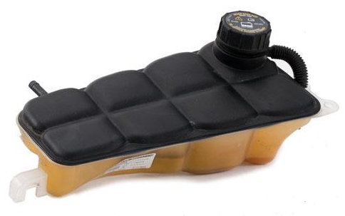
OEM 2008-13 C6 Corvette expansion tank
The Chevy Corvette that introduced the LS series engine deployed a cooling system with both a surge (also called expansion, recovery, or recirculating) and an overflow (also called a puke) tank. The C6 2008-13 Corvette model 22801031 is two-tone plastic and no longer available as an OEM part, but aftermarket plastic knock-offs sell for around $120.

Moroso 63787 bolt-on for C5 Corvette
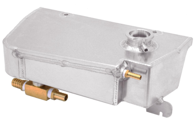
Canton 80-225 bolt-on for C5 Corvette
There are a few aftermarket aluminum replacements for earlier Corvetts, including the Canton 80-225 ($200 or $225 in black powdercoat) and the Moroso 63787 ($250) both designed as a bolt-on replacement for the 1997-04 C5 Corvette.
The Moroso tank fits the Corvette body profile, something we don’t need, and while the Canton design is universal and mounts along the chassis wall, its large size makes the fit into the XJ6 difficult. The Canton tank requires a specific 16 lb. pressurized cap (Canton 81-016 in regular or billet style).

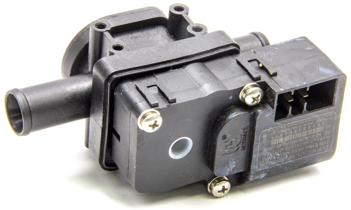
Canton 80-251 overflow tank
Overflow tanks are not pressurized and have only one inlet plus a bottom drain. Plastic models cost under $50 while aluminum tanks are about twice as much.
The Canton 80-251 is a good example of a cylindrical side clamp-mounting design with a choice of port configurations. Overflow tanks use simple non-pressurized caps.
C5/C6 style physical layout
Cooling system space planning requires both enough space to mount components like the surge and overflow tank (“OF” in the drawing below) as well as sufficient clearance for radiator hoses, firewall pipe pass-throughs, fans, and transmission cooling lines.
Most LS3 plumbing, including the water pump and steam pipe outlets, is located on the passenger side away from the lower steering column on the driver side. The 4L65E transmission cooling connections are also on the passenger side.

LS3 cooling system layout with most plumbing on passenger side
- transmission fluid cooling lines (driver side): outflow (green) to transmission and inflow (orange) back to cooler [this layout assumes an internal cooler integrated into the radiator body; note that 4L65E transmission cooler connection is on passenger side]
- main coolant hoses (passenger side): hot at top (thick red) and cool at bottom (thick blue)
- steam tube (passenger side): LS3 engine block to radiator top (cyan)
- overflow tank (passenger side): surge tank to overflow (blue); overflow drain not shown
- HVAC heater (passenger side): LS3 engine block to heater core (yellow) and return to surge tank (brown)
- surge tank (passenger side): outflow to LS3 engine block (rose), radiator (purple), and overflow tank (blue)
The large footprint of the Canton 80-225 unit presents a fitment challenge. Its large capacity, about a gallon (an additional overflow tank is not required here), and width barely fits along the engine bay wall in CAD mockups.

Canton 80-225 (in red) barely fits and may conflict with other components
C7 Corvette/Camaro style (2016+)
This configuration combines the surge and overflow tanks into a single recovery unit and uses a tee fitting to tie in the lines.
Similar to C5/C6 system except …
- LIGHT RED LINE: coolant exits water pump 5/8″ outlet to tee fitting that splits coolant into recovery tank (LIGHT BLUE LINE) and heater core (LIGHT RED LINE)
- ORANGE LINE: heater core coolant re-enters engine block via 3/4″ heater inlet
- DARK GREEN LINE: radiator vent port located at radiator cap connects to recovery tank; any air or steam in the system, especially from steam tubes, seeks highest point and flows out (in the event that system pressure exceeds cap pressure, recovery tank vertical feeder tube forces coolant into integrated overflow reservoir
C7 Covette/Camaro recovery detail
The 2016+ Camaro recovery tank integrates the surge functionality with the overflow tank into a single unit. The streamlined system eliminates some junctions that may leak and saves some space. Forfeited is the ability to dump excess coolant through the overflow tank drain (two small air holes enable “breathing” in the unpressurized overflow area).

OEM 2016 Camaro pressurized expansion tank with integrated overflow
C7 style physical layout
The Camaro recovery tank was specifically purpose-designed to fit into the Camaro engine bay and thus would require special mounts, if even possible, to work into the XJ6 engine bay.
In addition, the top of the recovery tank is not pressurized (just a plastic fill cap) which means that a pressurized radiator cap must be positioned at the highest point in the cooling system. The XJ6 radiator frame will sit well below the top of the LS3 engine, and this presents a potential air bubble problem. Jaguar employed a remote fill for this reason, and we should probably follow that decision.
Modified (Radium) Corvette style
A modified design retains the basic Corvette system but removes the radiator as a transfer point for steam bleeds. This system incorporates the Radium 20-0270-00 universal expansion tank; an separate overflow tank may be necessary due to the small Radium capacity.
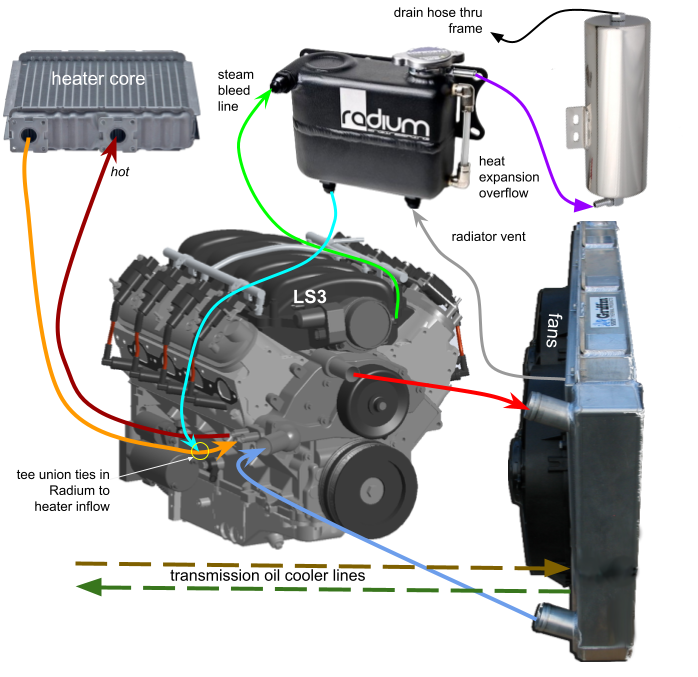
Similar to C5/C6 system except …
- LIGHT GREEN LINE: LS steam tubes capture air pockets that migrate up to Radium bleed port
- LIGHT BLUE LINE: coolant flows into water pump 3/4″ inlet from Radium recovery tank and joins main heater-to-pump ORANGE line via a tee barb
- DARK RED LINE: coolant exits engine block via 5/8″ water pump outlet port to heater core
- GREY LINE: radiator vents any air pockets into Radium
- PURPLE LINE: in the event that system pressure exceeds cap pressure, Radium bleed outlet at filler neck forces coolant into overflow reservoir
Radium recovery detail

Radium compact dimensions
The Radium tank holds about 25 fluid ounces. When the unit is filled half way, the expansion capacity of 12-13 oz before tapping into an overflow tank is slightly less than the likely 14-16 oz coolant expansion of the LS3 system, suggesting that more capacity in a separate overflow tank may be required. Alternatively, the Radium could be 1/3 filled leaving about 16 oz of expansion room … but this would need to be carefully managed and checked frequently. Fortunately, the Radium sight glass on the said makes a visual inspection easy to do.
We opted for a 21 oz overflow so filling the Radium tank to a precise level isn’t necessary. We’ll add coolant to the Radium up to the 80% level so 7-8 oz will flow into the overflow as the engine heats up and then flow back again as the engine cools down.
Radium with overflow physical layout
The small footprint of the universal Radium recovery system makes it easy to fit into the engine bay.
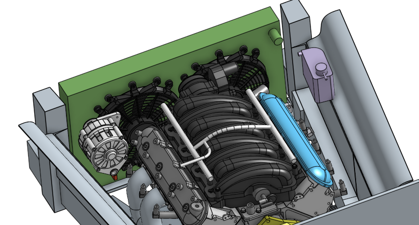
Radium recovery (purple) easily fits into engine bay
Installation
The Radium tank mounts on two long aluminum bars configured to also hold the overflow tank, a separate 21.6 oz overflow (KM-101) from Griffin Radiators. The overflow tube attachment runs to the bottom, so the overflow tube exits from the top.
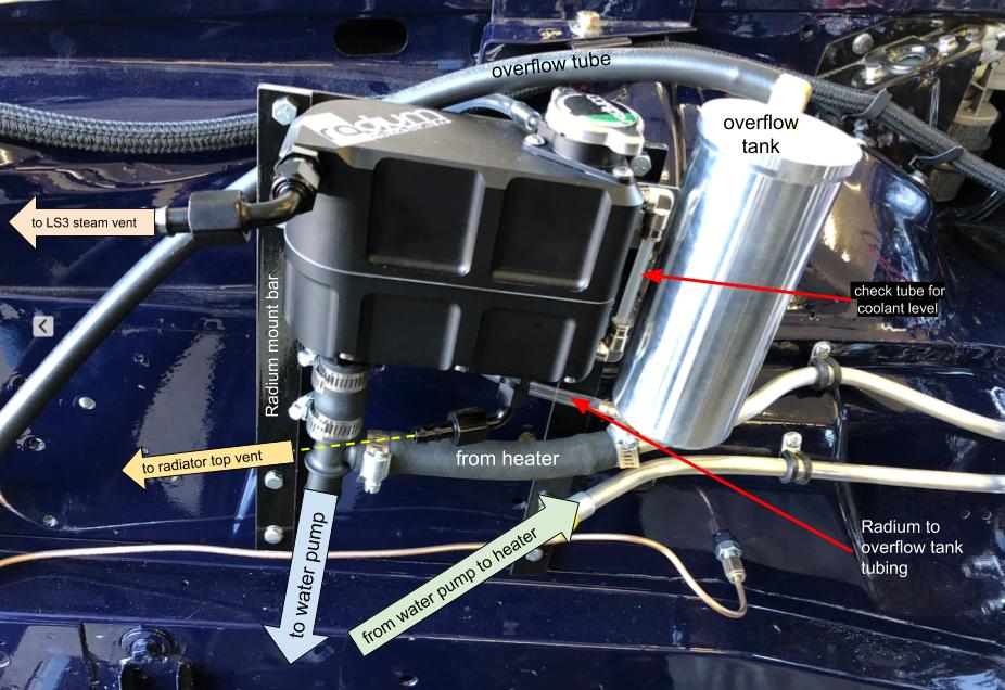
Radium install on right side of engine bay
Radiator requirements
The XJ6 radiator crossmember and chassis posts outline a 32.5 x 19.0″ rectangle (the frame tapers in towards the rear narrowing the width by one inch from 33.5″ at the front of the frame to 32.5″ at the rear) and this sets the outer limits for radiator size. In general, the larger the radiator, the better. Condenser connections (optimally on the passenger side) must be routed from the front of the radiator; if the radiator is symmetrical and centered, maximum width would be 31.00″ with a 3/4″ gap on each side.

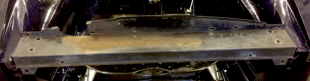
Crossmember “bump” profile
Radiators typically rest on vibration isolators (about 1/2″ cushion top and bottom) making the optimal height about 18.5″.
The radiator crossmember tapers, as noted above from 33.5″ to 32.5″ front to back, and it also has “bumps” on the left and right bottom corners that must be accommodated with either a rounded fillet or straight chamfer corner. Thus, a 31.0 x 18.5″ radiator with appropriate bottom fillet or chamfer corners is an exact fit.
XJ6 original specification
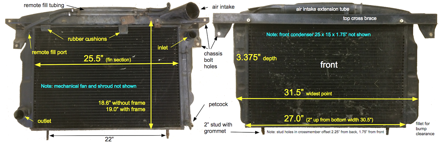
OEM XJ6 radiator with top cross brace attached
The original Jaguar XJ6 radiator does not have a top fill or pressure cap. Nearly all aftermarket radiators incorporate a pressure cap that protrudes above the top, a potential fitment issue that may require a cutout in the frame top cross brace.
The cross brace requires modification anyway because removal of the old air intake leaves a notch on the passenger side.
Radiator top cross brace with right side notch caused by removal of OEM air intake tube
Replacement options
Modern aluminum radiators are lighter and more efficient than the older copper-brass designs. Improved heat dissipation that can support up to 500 HP as well as passenger-side water pump connections become critical additional requirements for any replacement.

1982-92 Camaro style radiator fits the XJ6
Is there a stock radiator that fits? Well, the Chevy Camaro radiator, circa 1982-92, almost fits the Jaguar XJ6 frame with overall dimensions of 32 x 20″. The Jaguar radiator crossmember has “bumps” on the left and right thus further restricting the bottom width to about 28.5″ unless the bottom radiator corners are bevelled. The vintage Camaro radiator measures 30″ at the bottom with a top flare out to a full 32″, so if the top cross brace is eliminated, the Camaro radiator can fit … sort of.
However, the Camaro inlet/outlet ports must be relocated to the right side to fit the LS3 engine block. Transmission cooler functionality is also necessary, a feature that was not integrated into older radiators like the vintage Camaro ones.
An aftermarket radiator, either off-the-shelf or custom fabricated, appears to be the best solution.
Crossflow vs downflow
As the name implies, in a crossflow radiator, coolant is pushed by the water pump horizontally across the core from the inlet side to the outlet side. In contrast, downflow radiators uses vertical tubing from top to bottom.
Aluminum vs copper-brass
While both aluminum and copper are good heat conductors, aluminum is a harder and stronger metal. Aluminum tubing can withstand greater pressures so tube diameters can be larger, creating a more efficient heat exchange system. Aluminum weights about 60% less than copper as well.
Tube size vs number of rows
Coolant movement is the critical heat exchange parameter; there is a trade-off between tube diameter and the number of tubes, or rows, in the radiator’s design. Basic physics dictates that 2 rows with 1″ aluminum design equals the efficiency of 5 rows with 1/2″ copper-brass tubes. Of course, the larger the tube diameter, the thicker the radiator becomes. A one-inch aluminum has become the standard, but 1.25″ diameters can be used for higher horsepower (and heat) requirements. Extreme cooling needs are handled by a 1.50″ diameter tube, but the disadvantage is a thicker, heavier radiator.
Radiator aftermarket products
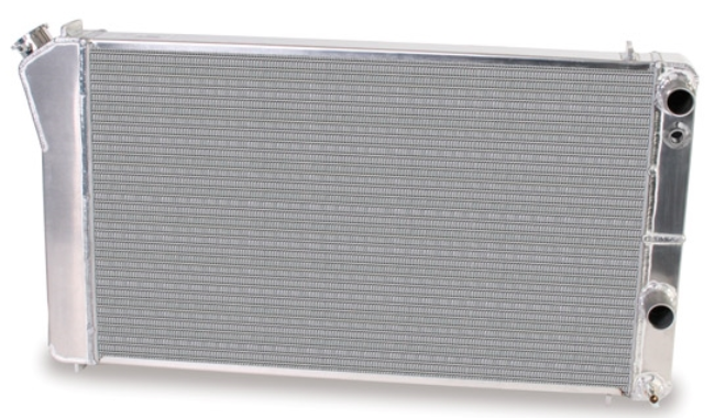
DeWitts

DeWitts 6139005A natural finish with trans cooler
The DeWitts 6139005A radiator, a drop-in replacement for the 1970-81 Camaro, measures 31 x 18.5″ with a fillet bottom and driver side flare to a 32″ top width; a passenger side flare would be optimal. Dual fans are included. This radiator has a crossflow design with 1″ tubes and incorporates an internal transmission oil cooler with passenger side connections. The angled pressure cap fill is easier to fit than a horizontal one.
Frostbite
Frostbite FB302 Camaro-style radiator
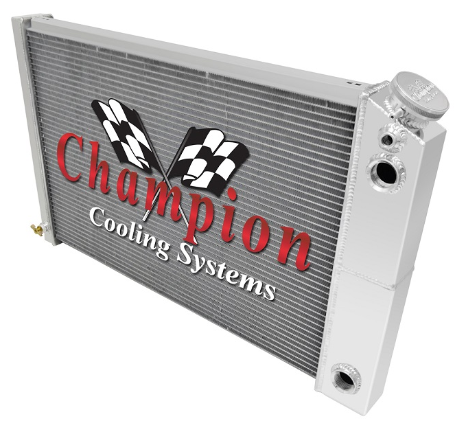
Champion CC162DP universal fit
The Frostbite FB302 is expressly designed for LS swaps, but does not include a transmission cooler for automatics; a separate cooler would need to be plumbed. Fans are not included, but a dual 12″ setup is available. The 31 x 18.5″ squared rectangle design (no top flare-out) presents a fitment issue. Crossflow design with undersized 11/16″ tubes and isn’t appropriate for the 430 HP LS3.
Champion
The Champion CC162DP measures 31 x 18.25″ for a 1970-81 Camaro drop-in with a square-bottom design that is more difficult to fit in the XJ6. This radiation incorporate a transmission cooler, but its undersized 0.63″ tubes, not intended for high horsepower applications, is a major issue.
AFCO
AFCO 84255 series
The ACFO 84255 measures 32.2 x 17.5″ so its a tight fit: with its lower height, it could be raised on vibration isolators to clear the crossmember “bump”. Crossflow with 1″ tubes, built-in transmission cooler, and single fan with shroud. $1250.
Flex-a-lite
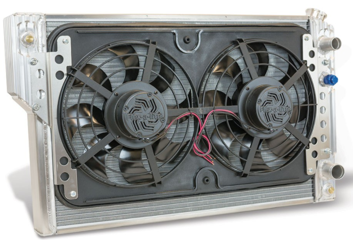
Flex-a-lite 56482LS with dual fans
The Flex-a-lite 56482LS measures 31.675 x 18.5″ and has connections for an optional transmission cooler. Bevel design presents no fitment issues. Includes integrated 12″ dual fans and shroud (7″ total depth with fans/shroud). $1100 + cooler.
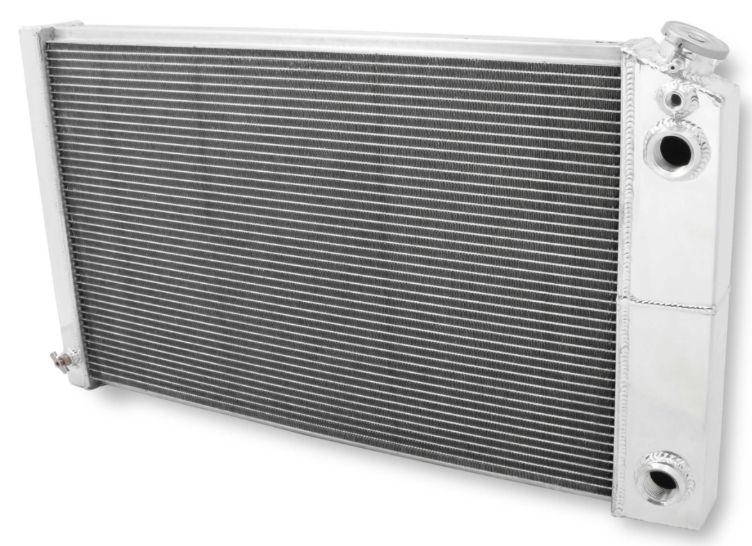
Griffin Performance

Griffin 8-70087-LS with internal oil cooler
The Griffin CU-8-70087-LS measures about 31 x 19″ with 1.25″ tubes arranged in 2 rows that also incorporates an internal transmission oil cooler. The transmission connections are on the driver side while all other connections are on the passenger side. Fitment difficult due to the square corners. Depth of radiator/fan/shroud combo is 5.7″. (See also Custom built radiator below built by Griffin.)
Be Cool
The Be Cool 62231 at 31 x 19″ has beveled corners. An automatic version with transmission cooler is available. About $700 without fan or shroud.
Custom built radiator
Standard aftermarket radiators don’t quite meet our needs. So we designed a LS3-XJ6 radiator and Griffin built one to our exact specifications. This custom part provides an exact fit with connections placed in optimal locations.

Custom Griffin radiator meets all requirements
No filler cap matches original the Jaguar specification, and placement of cooler lines on passenger side reduces engine bay clutter. The Radium recovery tank serves as the remote filler with the only pressure cap in the system and LS3 steam tubes connect to Radium instead of the radiator.

Top mounting tabs
Two 1/8″ aluminum mounting tabs are inserted through the top cross brace and are connected across a foam filled gap to provide some vibration and insulation protection.
This is necessary to prevent electrolysis, the corrosion caused by any electrochemical charge across the aluminum infrastructure of the radiator. The radiator must be physically isolated from the grounded chassis frame at all points. There is an air gap on all sides of the radiator.
Along the radiator bottom, the strongest structural area, two threaded pins are secured through holes in the bottom cross brace. The pins fit through plastic distance pieces and rest on rubber bumpers for both vibration dampening and electrical insulation.
Cost comparison
Surprisingly, a custom built radiator costs only a small premium over a standard off-the-shelf product. Dual fans and shroud cost about $400 and an oil cooler is $100-150. Thus, high capacity standard offerings fully outfitted with fans, shroud, and oil cooler fall into a $1000-1250 range.
LS SWAP RADIATORS
| Mfg/Model | Disadvantages | Cost |
|---|---|---|
| DeWitts 6139005A | driver side flare|redundant temp sensor port | $1000 |
| Frostbite FB302 | no cooler|low capacity | $850 + cooler |
| Champion CC162DP | low capacity | $550 + cooler |
| ACFO 84255 | driver side flare and fill | $1250 |
| Flex-a-lite 56482LS | driver side flare|separated HVAC refrigerant lines | $1100 + cooler |
| Griffin CU-8-70087-LS | too tall with protruding fill cap | $800 |
| Be Cool 62231 | fitment depends on bottom bevel | $700 + fan/shroud |
| Kriss/Griffin custom | perfect fitment | $1300 |
Fans

Griffin LS swap “combo” with dual Spal fans
The powerful LS engine requires electric fans because a mechanical single fan linked to engine revolution doesn’t provide sufficient air flow through the radiator. A dual fan setup can generate over 3000 CFM that will handle the 430 horsepower LS heat generation. A custom shroud is also required. Most manufacturers offer a “combo” unit with fan/shroud engineered to fit the radiator body. Dual fans require a substantial current draw that, at peak, can be around 35 amps.
Connections
There are a number of cooling connections that require special fittings, adapters, and hose/pipe/tube specifications:
- transmission fluid cooling
- main radiator coolant flow
- steam tube bleed line
- HVAC heater core and refrigerant lines
- recovery and overflow tank
SUMMARY OF LINE TYPES AND FITTINGS
| Connection | Start | Line type | End |
|---|---|---|---|
| transmission to radiator | 9/16-18 thread to -6AN male adapter | braided stainless with -6AN female | -6AN male-to-female |
| radiator inflow (bottom) | 1.50" pipe barb | rubber hose with clamp | 1.50" pipe barb |
| radiator outflow (top) | 1.25" pipe barb | rubber hose with clamp | 1.25" pipe barb |
| LS3 steam tube to Radium | -6AN with 3/8" barb | rubber hose | 1/4" barb |
| Radium inflow to water pump | 3/4" barb | rubber hose with tee | 3/4" barb |
| heater inflow to water pump | 5/8" barb | alum/rubber hose | 5/8" barb |
| water pump outflow to heater | alum line 5/8" barb | alum line/rubber hose | 5/8" barb |
| radiator vent to Radium | 3/8" barb | rubber hose with clamp | 3/8" barb |
Upper and lower radiator hoses
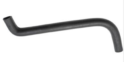
Dayco 71994 upper hose

Dayco 72239 lower hose
Molded rubber radiator hoses provide more of an OEM look. It’s takes a little research to find a hose that will fit the unique profile of the XJ6 with the LS3 engine.
One method is to bend hanger wire into the exact centerline shape required for the upper and lower hoses. Then visit your local auto supply store and spend time in the back storeroom trying to match a hose to the hanger wire profile.
Fortunately, we found two very good fits — Dayco 71994 and 72238 — originally produced for the 2000-01 and 2002-12 Dodge respectively. With a little trimming, both hoses fit extremely well.
HVAC heater/evaporator
The HVAC system uses three different diameter refrigerant hoses: #10 low pressure vapor from the evaporator to the compressor; #8 high pressure liquid from the compressor to the condenser; and #6 from the condenser to the evaporator. Heater and refrigerant hoses pass through the firewall via bulkhead plates to the Vintage Air Gen II ComPac HVAC unit. Plumbing with an internal or external drier are shown.
Heater and refrigerant connections to Compac Gen II with drier outside the firewall

Connection to Compac Gen II with internal drier
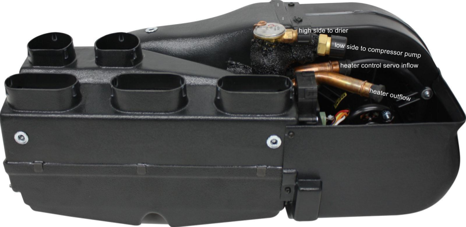
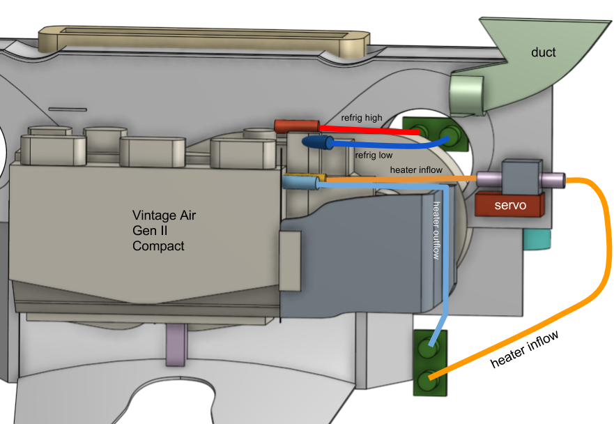
Vintage Air ComPac plumbing connections
The heater inflow tube, which takes a 5/8″ I.D. rubber hose, is the one closest to the fan housing running parallel to the Compac body.. The heater tube at a 45 degree angle is outflow.
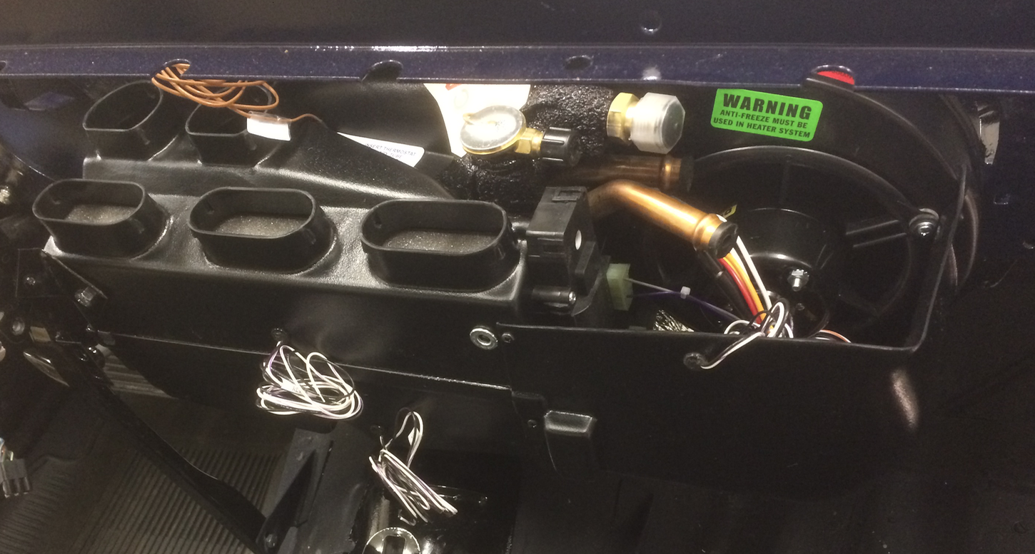
Compac Gen II connections: #10 A/C line at top and heater inflow directly below
A/C condenser
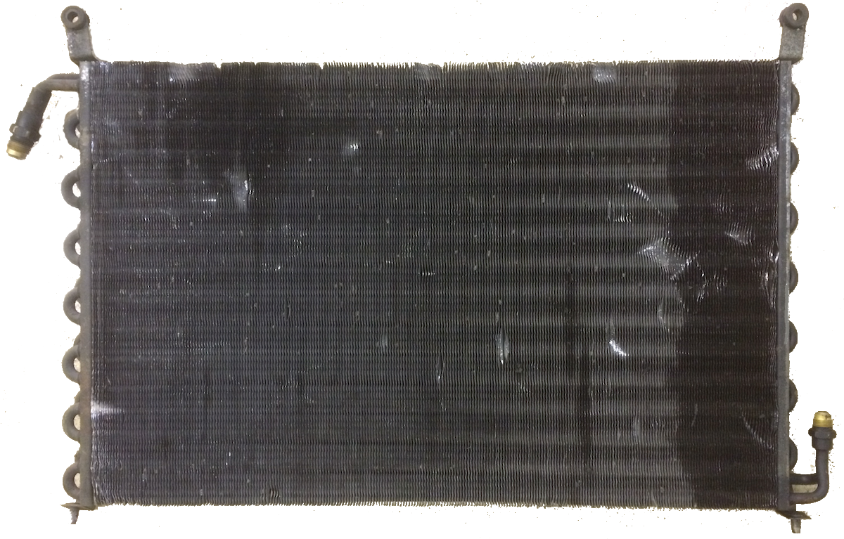
XJ6 condenser designed for CFC-12 refrigerant
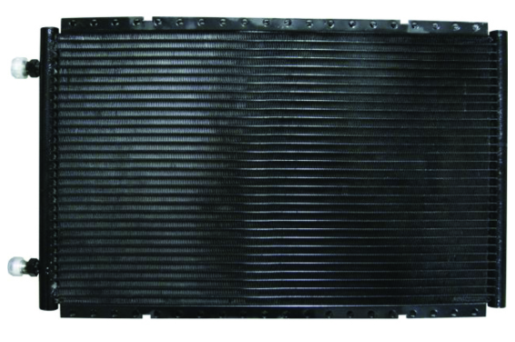
Vintage Aor 03770-VUC
The original XJ6 condenser measures 25 x 15 x 1.75″ and was designed for the now obsolete CFC-12 refrigerant infamous for its ozone-depleting characteristics. A replacement condenser will use the more benign HFC-124a chemical.
The XJ6 condenser has connections at the lower left for the drier and upper right for the A/C pump on the driver side of the Jaguar engine. On the LS3, the pump is located on the passenger side.
The Vintage Air 03660-VUC has male O-ring fittings — #8 on top and #6 at the bottom — all on the passenger side, and its 25.5 x 14 x 0.8″ dimensions provide an excellent fit.


Presently working on an XJ6C resto-mod, using the stock engine. Simplifying and upgrading components under the hood and working my way back. Your site is an invaluable resource for exposing the reader to the products out there that can solve virtually every issue that will arise. First saw your link on the ultra snooty Jaguar Forum. Thanks for taking on this monumental task and hopefully your site will give guys like me that added information to get our projects completed in our lifetimes…