Topics
About CAN bus
In 1986, Robert Bosch GmbH, the German engineering and electronics company with a long time focus on the automotive industry, introduced a CAN bus protocol that launched the “smart car” era at the Society of Automotive Engineers congress. Prior to 1986, all automotive wiring was “dumb” in the sense that physical wires transmitted power but not data, and electronic modules didn’t readily communicate with each other.
It took over a decade for CAN bus to become an industry standard (with many proprietary configurations that continue to evolve), but since 2008 all U.S. cars have at least a rudimentary CAN bus “smart” infrastructure.
Basically, CAN bus made it possible for many different electronic controls — for example, engine management, automatic transmission shifting, cooling/heating regulation, power windows, and entertainment features — to work together in a coherent command structure. Before CAN bus, automotive wiring employed a hub-and-spoke topology much like the Boston subway … and like the subway, as long as there weren’t too many spokes, the network was relatively efficient. But since many modern cars package together over 50 different modular units, a CAN bus arrangement is vital.

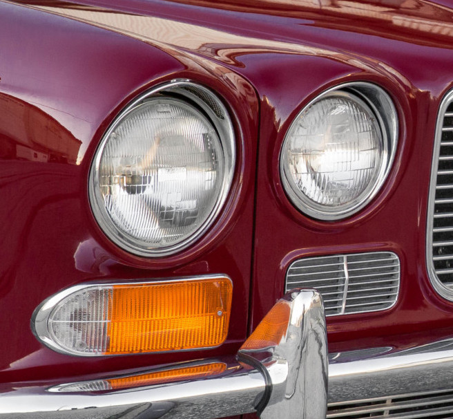
1972 XJ6 wiring schematic
Of course, when our Jaguar XJ6 was manufactured in 1972, the wiring was entirely “dumb” and consisted of hub-and-spoke fuse and circuit boards controlled by switches, flashers, and mechanical relays.
Complexity became a constraint: long strands of thin wire had to run the length of the car, across the floor pans, and around the engine bay. Diagnosing faults became a major nightmare while mechanical components suffered from environmental stress. In particular, Jaguars of the 1970s earned a reputation for unreliable electrical systems with fussy wipers, inadequate HVAC, and inaccurate instrumentation. Perhaps that’s why the XJ6 was outfitted with two fuel pumps … just in case.
Aftermarket CAN bus
The aftermarket tends to lag behind when it comes to electrical/electronic systems at least in part because the builder community lacks much of an electrical engineering background. However, one company — I Squared Engineering — pioneered its “1+1” and “Million Mile” smart harness during the early days of CAN bus standardization (around 2005-06). In 2007, I Squared teamed up with Littelfuse, a public circuit protection company, to launch a CAN bus architecture regrettably named “ISIS”.
Apart from the name, ISIS struggled to define what it was to an audience that didn’t know a CAN bus from a can opener. Today, the system is marketed as Infinitybox by an independent LLC (although some documentation still carries the old ISIS brand). At this point, Infinitybox doesn’t have direct competition from major aftermarket harness companies like Ron Francis or Painless, and despite its odd-man-out marketing challenge, Infinitybox offers a unique system for customized CAN bus smart wiring.
Infinitybox architecture
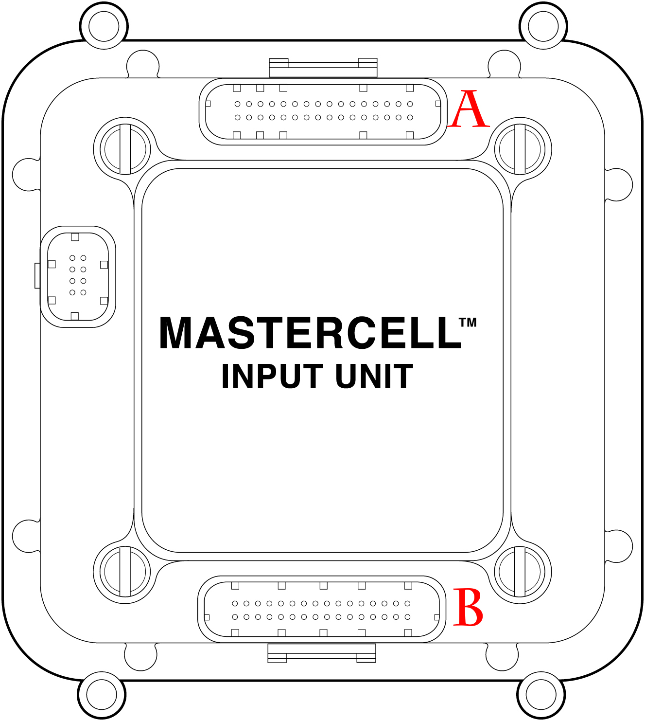
Infinitybox Mastercell
Infinitybox employs two different circuits — 12 and 5 volts — to communicate with and control various components. The central “brain” is called Mastercell and it is only connected via a 5-volt CAN bus cable with an 8-pin connector (on the left in drawing) to either 12-volt outputs, called Powercell, or other units like inMOTION that can control reverse polarity motors (power windows and door locks, for example). Mastercell controls by switching ground only and cannot handle a 12-volt input. It has two harness banks, A and B, each with 32 wire pinouts. If a switch is not ground triggered, an inverter (known as inVERT) or a relay must be used to enable ground switching.
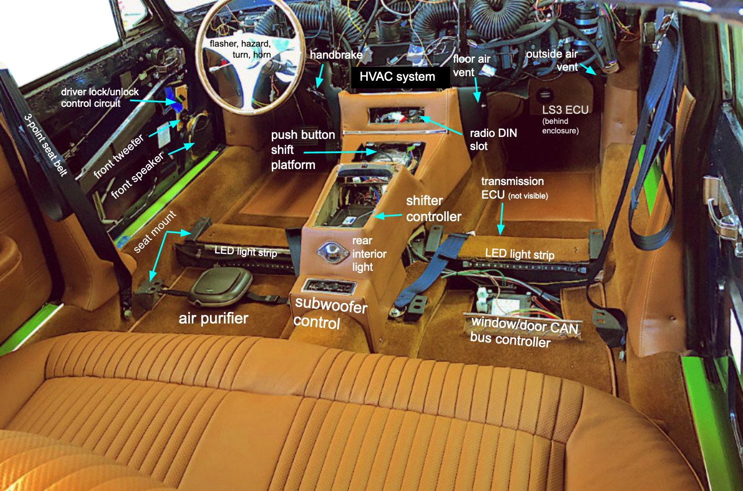
One advantage of the Infinitybox architecture is that a single CAN bus cable (light green line below) runs from the trunk to the dash instead of a large wire harness for rear lights and fuel pump. This doesn’t eliminate all other wires (for example, leads from the fuel level sender in the rear tank still needs to go to the fuel gauge in the dash), but it greatly simplifies the task. This is particularly helpful with our planned trunk-mounted battery design.

A trunk mounted Powercell connected to a Mastercell via a single CAN cable provides 12 volts to all rear lights, the heated backlight, the fuel pump, and the trunk lock popper. CAN bus messages then control switches on the dash via ground switching or communicate directly with the engine ECU.
LS3 and Supermatic ECU
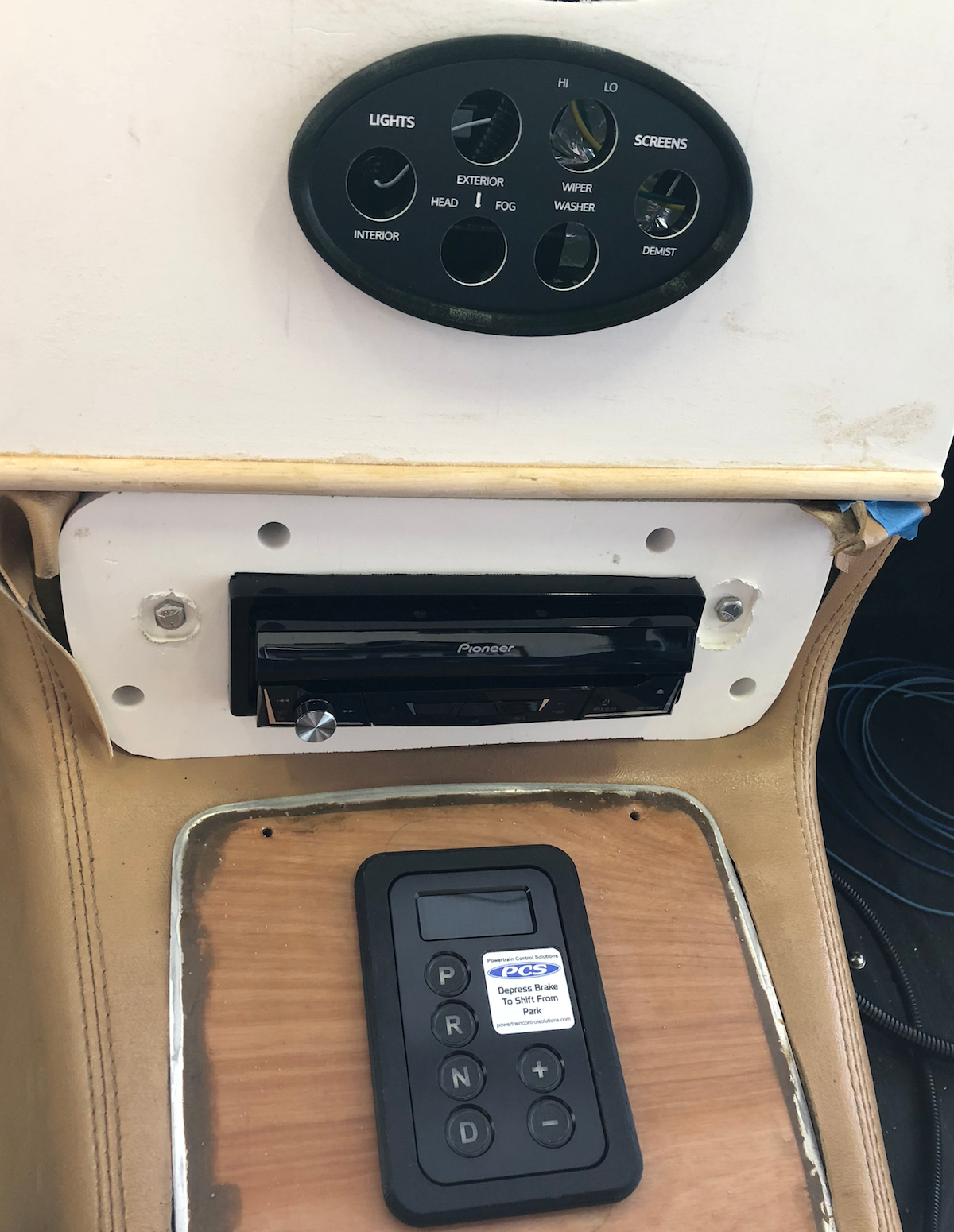
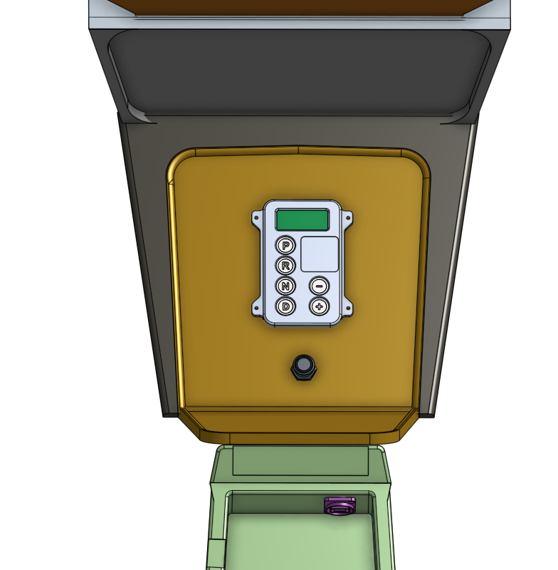
A separate CAN bus circuit connects the engine and transmission ECUs, sharing information along the way with the Vintage Air HVAC system, Dakota Digital gauges, and PCS electronic shifter.

A pigtail output from the Supermatic tranmission ECU enables a Windows PC interface. This is used to monitor engine/transmission data and also permits customization of the “sport mode” shift profile.
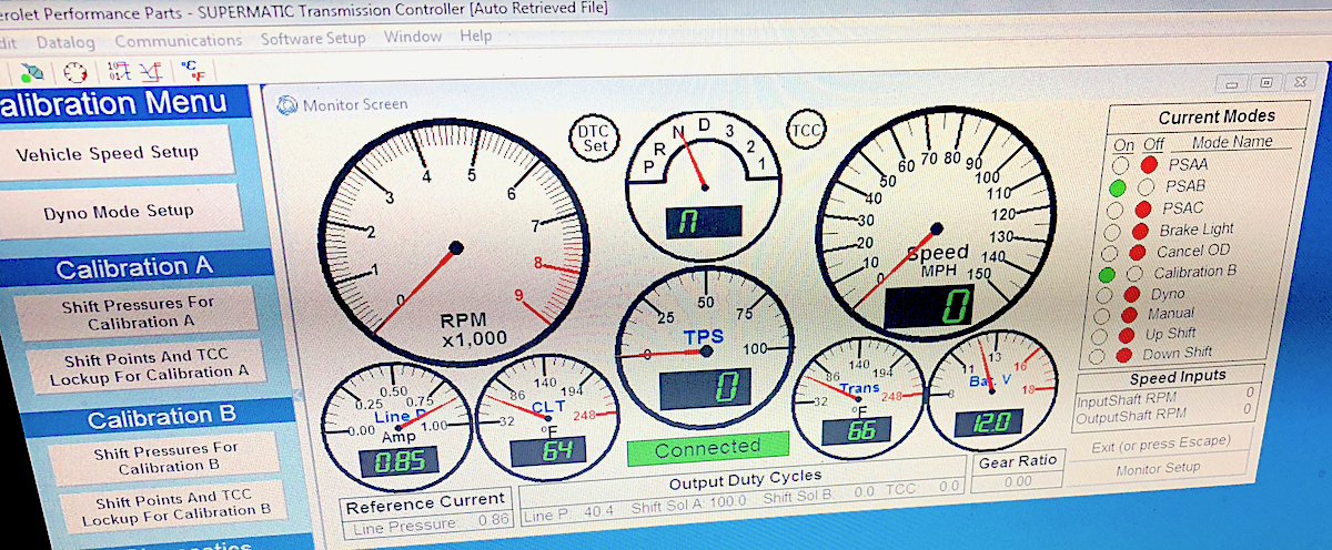
Windows PC interface with Supermatic ECU