Topics
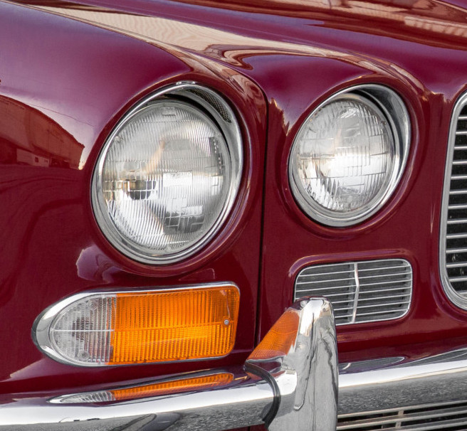
Original LHD layout
The British right-hand drive legacy forms a kind of “British car DNA” because design considerations always began from the RHD perspective. Jaguar often seemed to take shortcuts when it came to re-designing for the American left-hand drive market. The failure to reposition the front hood release to the left driver side for U.S. exports is one example. Another is the rather convoluted brake line layout in the LHD XJ6.

To maximize compatibility with RHD models (perhaps motivated by manufacturing cost control?), the LHD XJ6 used a cumbersome left-to-right crossover of brake lines for both front and rear. As a result, the front lines crossed the engine bay twice, much in the same manner as the earlier MK saloons, while the rear lines transversed the firewall and were run up the right side of the undercarriage.
Modified LHD layout

3/16″ brake line clip
A simplified layout uses an engine bay crossover along the firewall and runs the rear lines along the right undercarriage to take advantage of the rear flexible line mounting tabs on the chassis and rear suspension cage.
Running brakes lines along the undercarriage right side means that the fuel lines, which run along the left undercarriage given the fuel tank configuration, will be isolated in their own track. The 1/0 AWG battery cable will also run on the right side.

Since we’ve installed a Series 3 master cylinder with metric thread, the connection specifications need to be modified as well.

A new 10x1mm DIN flare 3-way tee fitting replaces the original Imperial threads. The original brake calipers accept 3/8″ UNF threads, so the layout uses a mix of both UNF and metric. The master cylinder has ports of different sizes — 10mmx1 and 12mmx1 metric — presumably to help mechanics sort out the front from the rear system!
Flare end nomenclature is so confusing that it’s easier to refer directly to the brake line flaring tool itself. There are two die sets: metric DIN and imperial SAE. The DIN die has only one operational face, called “OP1”, so all so-called DIN flares have a single press action. These are used only for male metric end fittings.
The calipers use UNF male fittings with the so-called “British bubble flare” formed by the SAE die “OP1” face only; thus it too is a single press action.
Finally, the female metric end fittings use the SAE die with both OP1 and OP2 faces, so this is a double press action. How confusing! The metric female end, which is typically referred to as “DIN”, is actually fabricated with a SAE die and not with a DIN die!
The system uses three flex lines with metric threads — one in the rear and two in the front — that connect the 3/16″ hard pipes. Only one rear flex line is required because in-board rear brakes mount directly to the suspension cage.
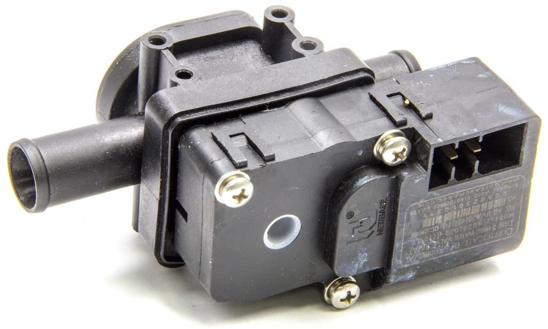
Servo and master cylinder
Due to limited availability of the old Series 1 servo and master cylinder combination, we upgraded to the new Series 3 version. There are modest changes, like the slightly longer length of the servo housing and the added convenience of a top mounted reservoir that replaces the awkward remote reservoir (one less connection that could leak brake fluid).
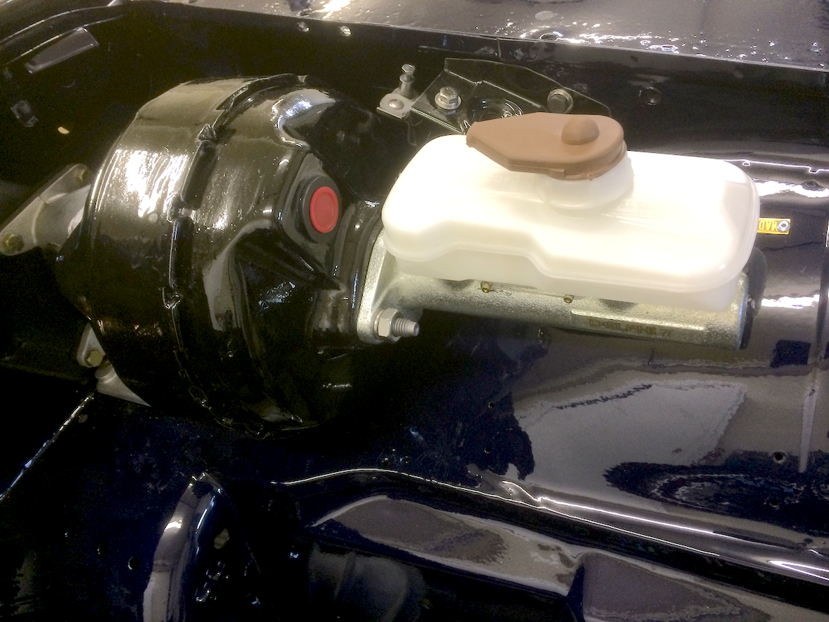
XJ6 Series 3 servo and master cylinder with top mount reservoir; note 10mm and 12mm port hole threads
Speed bleeders

Goodridge 3/8-24 speed bleeders
Speed bleeders enable one-person brake fluid air bubble elimination. It’s an inexpensive way to make sure that brake lines operate at peak efficiency. Front bleeders are simply installed in the regular bleeder threaded hole. For the rear, we’ll also add a short remote brake line so that the bleeders are more readily accessible.
Installation

High quality flaring tool
Proper installation of brake lines requires a correct pipe flare (unless you install a pre-cut set … not possible for our restomod project). Fortunately, Federal Hill rents a high quality English flaring tool for only $25 that handles the job with precision (retail price is over $400 with dies).